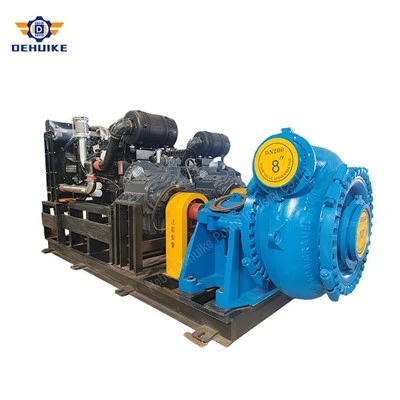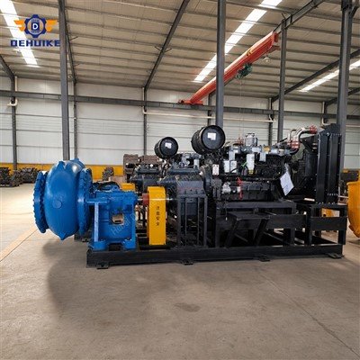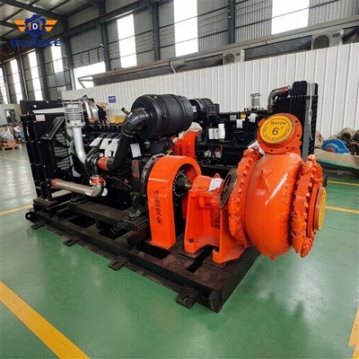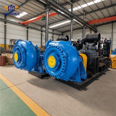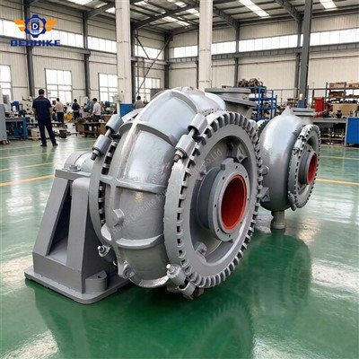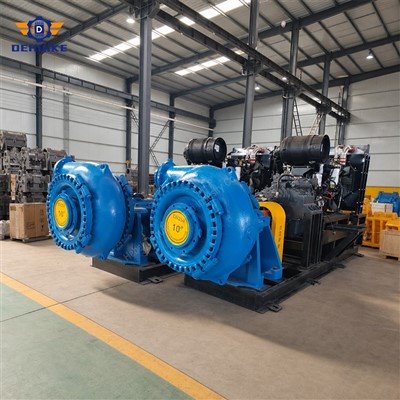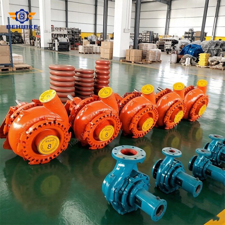
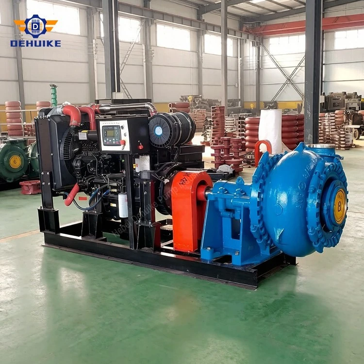
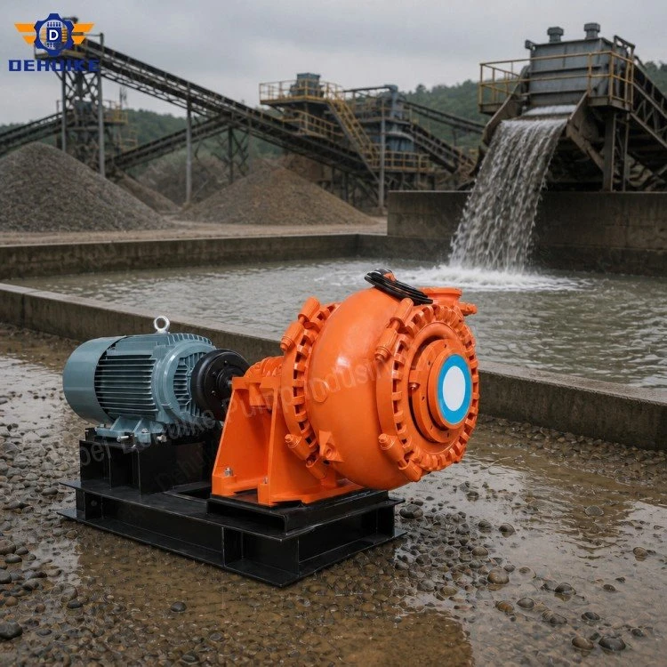
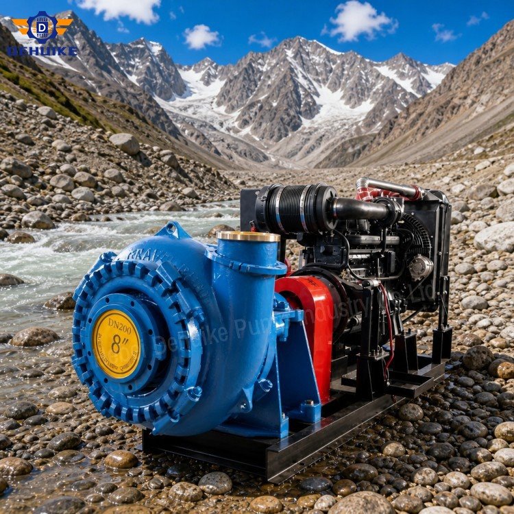
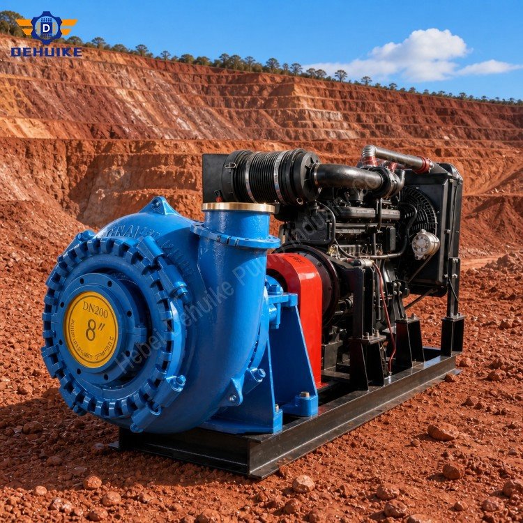
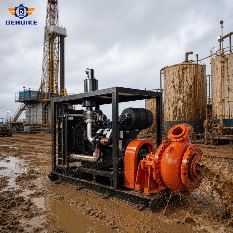
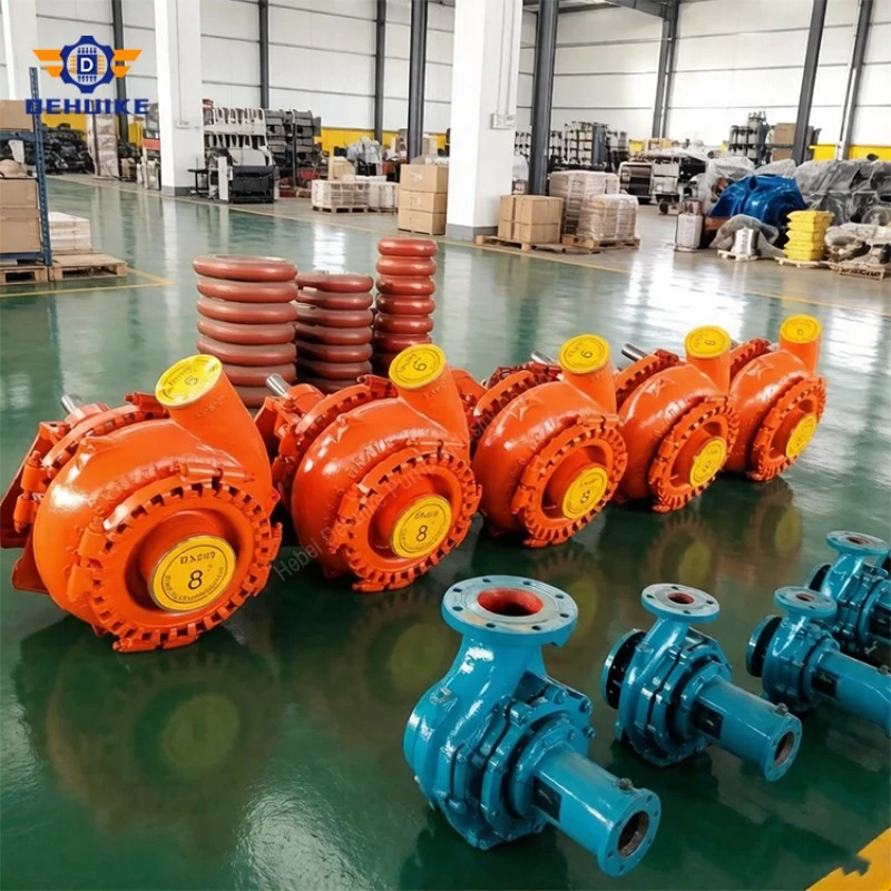
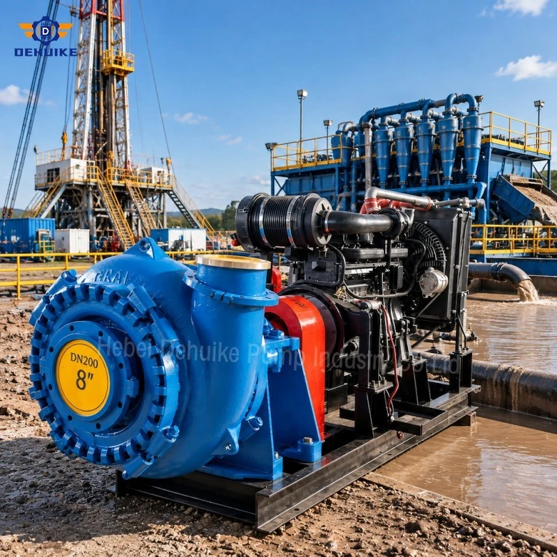
Hebei Dehuike Pump Industry Co., Ltd. is one of the most reliable manufacturers and suppliers of long distance sand and gravel pump in China. With abundant experience, we are committed to providing high quality customized pumps with competitive price. Welcome to wholesale bulk long distance sand and gravel pump for sale here from our factory. Also, pricelist is available.
Introduction | Treat Distance As A Hydraulic Design Variable
A Long Distance Sand and Gravel Pump supplies energy to a solids-bearing stream that must travel through an extended pipeline. Distance matters because friction accumulates along every straight section, while elevation, fittings, changes in diameter and terminal pressure add separate demands. A route that appears workable at start-up can move to a different operating point after pipe is added or the discharge area is relocated.
The five G Series points on this page support preliminary comparison across several flow and head scales. A Long Distance Sand and Gravel Pump is selected from the intersection of a verified pump curve and the calculated system curve, not from pipeline length alone. Slurry correction, power, suction condition, pressure limits and transport stability must be checked for the same operating case.
Where the mixture includes coarse gravel, a Heavy Duty Gravel Pump may provide a suitable construction and passage class. It does not remove the need to define grading, concentration and foreign-object controls. Long routes amplify the consequences of a poor solids definition because deposition, clearing time and component wear can occur far from the pump station.
Specifications / Technical Data | Convert The Route Into Traceable Pressure Segments
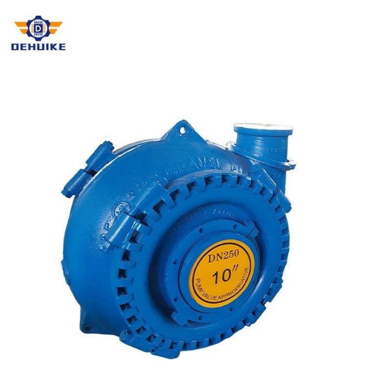
The physical data and hydraulic coordinates below are copied from complete, selected G Series product data. Capacity, total head, rotational speed, point efficiency and motor entry remain tied to one original record for each model. The source does not state pipeline length, internal bore, roughness, slurry properties, elevation profile, pressure rating, booster arrangement or guaranteed transport distance.
|
G Series model |
Particle reference (mm)* |
Suction size (mm) |
Discharge size (mm) |
Pump weight (kg) |
|
6/4D-G |
82 |
150 |
100 |
460 |
|
8/6E-G |
127 |
200 |
150 |
1120 |
|
10/8F-G |
178 |
250 |
200 |
2250 |
|
14/12G-G |
241 |
350 |
300 |
5400 |
|
16/14-G |
255 |
400 |
350 |
6950 |
|
G Series model |
Mixture flow (m3/h) |
Total head (m) |
Speed (r/min) |
Point efficiency (%) |
Motor entry (kW) |
|
6/4D-G |
158 |
50.5 |
1480 |
52 |
75 |
|
8/6E-G |
410 |
43 |
1400 |
60.8 |
110 |
|
10/8F-G |
670 |
42 |
980 |
49.3 |
220 |
|
14/12G-G |
2320 |
56.5 |
700 |
64.2 |
900 |
|
16/14-G |
2249 |
40.4 |
500 |
64.5 |
800 |
The particle field is a catalogue reference, not a continuous-feed promise. The product data does not define shape, distribution, test method or near-limit frequency. Confirm its meaning and compare the accepted feed with the pump internals, valves, reducers, bends, couplings and every downstream restriction before specifying the line.
Divide the route into calculation segments at every change in diameter, material, elevation slope or fitting density. For each segment, record internal diameter, length, roughness basis, slurry case, local-loss coefficients and start/end elevation. This makes the total dynamic head auditable and shows which portion of the route consumes the largest margin.
Generate a system curve for the initial route and every planned extension stage. Friction varies with flow, so adding a fixed head allowance to the selected table point is not an adequate long-distance method. Plot each route curve against the supplier's corrected pump curve and retain the intersection, absorbed power and acceptable operating-zone check.
Prepare at least three mixture cases: flushing liquid, expected production slurry and the highest credible solids condition. Use consistent concentration and density definitions. The case with the greatest friction may not be the case with the highest motor load, and the case most likely to deposit can occur during reduced throughput rather than peak production.
If one station cannot cover the route, partition the pipeline into pressure zones. Calculate the suction and discharge pressure of the primary pump and every booster at a common flow. Check maximum allowable pressure near each station and minimum inlet pressure at the next. Pipe, hose, joint, valve and casing limits must be evaluated separately rather than represented by one generic line rating.
Create a station coordination table listing speed range, start permissives, shutdown sequence, minimum flow, control signal, trip action and communication status. Pumps in series share flow but contribute different head. An unmatched speed change can overload an upstream pressure boundary or starve a downstream station even when the combined head appears sufficient.
Review transient cases in addition to steady operation. Sudden stopping, valve movement, power loss, line draining, restarting against settled solids and booster trip can create pressure or torque conditions absent from the normal duty calculation. The required surge study and protection method depend on route profile, pipe properties, controls and slurry behaviour.
Maintain a distance-stage register from project commencement to the longest forecast route. Useful fields include chainage, installed pipe length, static lift, calculated friction, terminal pressure, active stations, selected speeds, expected flow, corrected power and remaining pressure margin. Update the register after field measurements rather than treating the original design as fixed.
Assess energy per unit of accepted solids, not only motor kilowatts at one catalogue coordinate. Combine measured input power, mixture flow, density or concentration, operating hours and delivered dry-solids basis over the same period. This reveals whether extra speed is producing useful transfer or mainly moving additional carrier water through an increasingly resistant route.
The motor entries shown belong to the listed source points. Final driver selection requires corrected absorbed power, mixture density, transmission loss, service margin, ambient and starting method. Request the full performance curve and permissible speed range; one table coordinate cannot demonstrate that a Long Distance Sand and Gravel Pump will remain suitable throughout route growth.
Product Detail | Understand How The Operating Point Moves As The Line Grows
The impeller transfers mechanical energy to the mixture, and the casing converts part of the velocity into pressure. The pipeline then spends that energy overcoming elevation and resistance. Because friction rises nonlinearly with flow, the system curve changes shape when pipe diameter, length, roughness or slurry properties change.
For a Long Distance Sand and Gravel Pump, the operating point is not permanently fixed by the pump model. Extending the route generally raises resistance and moves the intersection toward another flow-head condition. Wear, internal clearances and process variation can move the pump curve at the same time, so commissioning data should be compared with both curves.
Pipeline geometry also influences solids distribution. Long horizontal sections, high points, low pockets and abrupt transitions deserve separate review for deposition, air accumulation, drainage and clearing. The available product data gives no pipe design, pressure envelope or control philosophy; those elements belong to the engineered transfer system.
Features / Equipment Characteristics | Preserve Transport Through Normal And Reduced-flow States
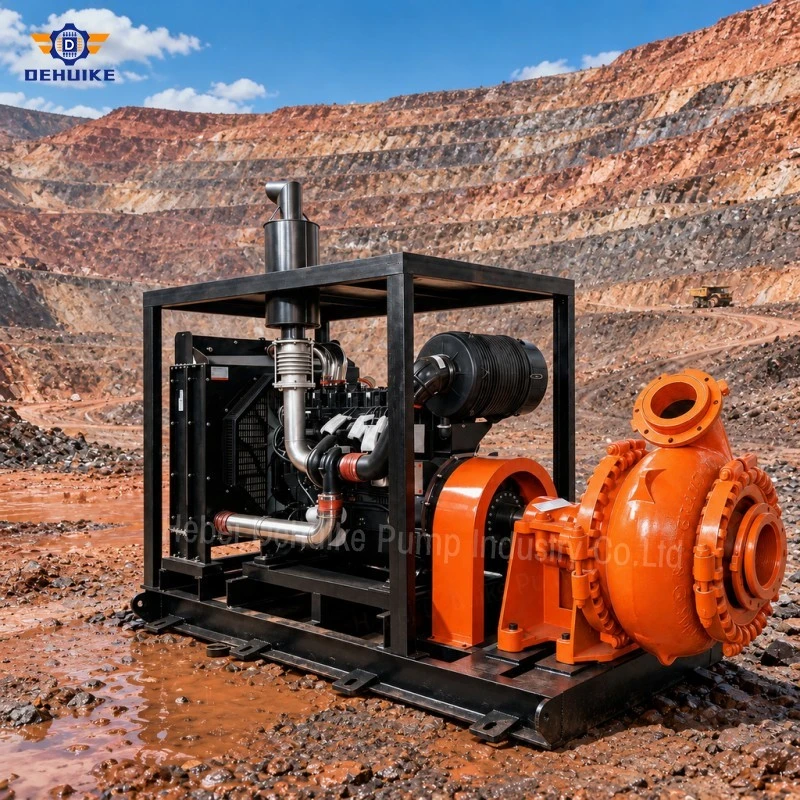
Long-distance slurry transport is governed by more than the full-production condition. Start-up, controlled turndown, temporary feed loss and shutdown can create lower velocities or uneven concentrations. The operating philosophy should define how the line remains transportable across these states.
-Model route stages separately. Initial, intermediate and final pipe configurations should each have a documented operating intersection and pressure profile.
-Define the transport window from project data. Pipe bore, grading, density and concentration determine deposition risk; one universal velocity is not used.
-Coordinate series stations. A Heavy Duty Gravel Pump booster must share the same mixture flow and an agreed control and trip sequence.
-Plan flushing and restart. Water availability, drain points, isolation sections and settled-material handling should be established before production.
Instrumentation should make route changes visible. Pressure readings at station boundaries, flow, density, speed and power can distinguish rising line resistance from altered feed or pump wear. Data timestamps and sensor elevations matter; isolated readings without route configuration can lead to the wrong corrective action.
Our Advantages | Compare Delivered Solids Over The Complete Route Life
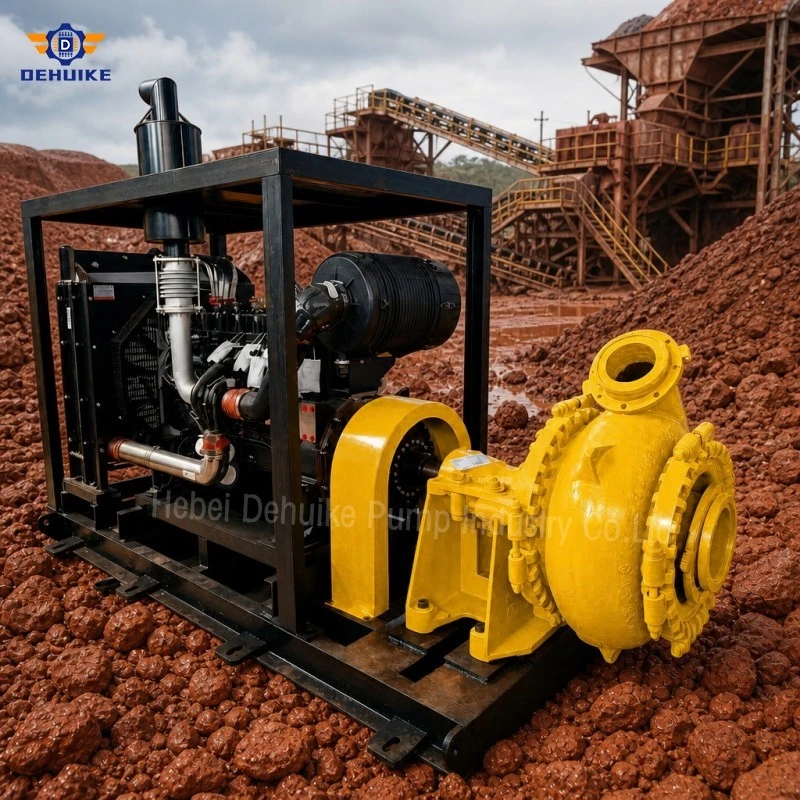
A Long Distance Sand and Gravel Pump proposal should be compared on delivered solids, energy, availability and route adaptability. Include booster consumption, flushing water, pipe handling, blockage clearing, wear parts and production lost during extensions. A lower first cost can be offset by frequent intervention if the final route was not included in the selection basis.
A shared calculation register improves procurement transparency. Each Heavy Duty Gravel Pump offer can be checked against the same route stages, slurry cases and pressure boundaries. Assumptions then remain visible instead of being concealed inside broad distance claims such as suitable for several kilometres without diameter, elevation, flow or solids context.
Production Process And Quality Assurance | Freeze The Configuration Used For Curve And Pressure Review
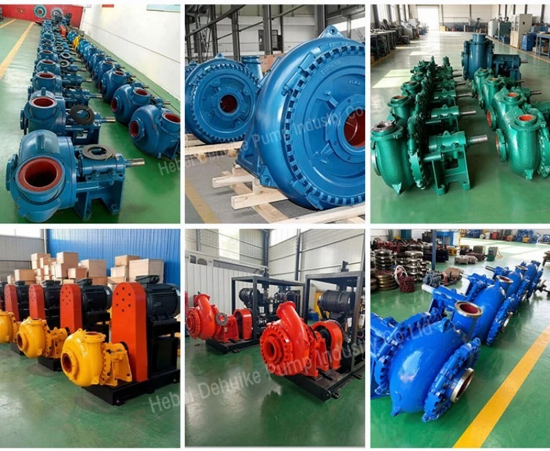
Release manufacture against an approved model, impeller arrangement, casing orientation, wetted-material schedule, seal plan, shaft configuration and driver interface. Where the package includes a base, coupling, guard, gearbox or instruments, identify the boundaries and connection data.
Tag each Long Distance Sand and Gravel Pump and its major loose components to the approved station duty. Similar external dimensions do not prove that impeller identity, speed limit or material matches the submitted curve. Packing and preservation should protect nozzles, machined interfaces and instruments until installation.
Quality assurance: verify pump evidence without claiming pipeline performance
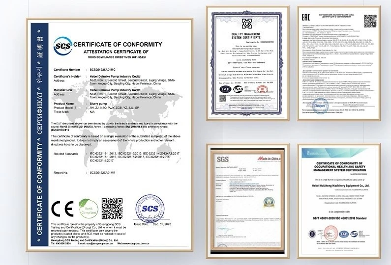
Material documents, dimensional inspection, balance records and a defined hydraulic test support different acceptance claims. A clean-water test can verify agreed reference points under a stated build and speed. It does not reproduce field slurry, kilometres of pipe, booster interaction, line transients or deposition behaviour.
The available product data contains no test standard, curve tolerance, casing pressure class, material certificate, vibration criterion or long-distance guarantee. Put required documents and witnessed tests into the purchase specification. A Heavy Duty Gravel Pump test remains evidence for the agreed pump configuration; complete-system acceptance should use site instruments and route cases rather than extending that test beyond its scope.
Applications | Adapt Station Architecture To The Route Profile
A Long Distance Sand and Gravel Pump may be evaluated for permitted dredged-material placement, aggregate transfer, quarry overburden, mine tailings containing coarse fractions and construction slurry conveyance. The examples below illustrate selection logic and are not documented customer installations or promised field results.
Smaller-volume route with significant static lift
The 6/4D-G point lists 158 m3/h at 50.5 m, while the 8/6E-G point lists 410 m3/h at 43 m. Their higher listed speeds require a careful wear and corrected-power review. Route length cannot be inferred from head because pipe diameter, elevation and slurry resistance determine how that head is consumed.
Intermediate transfer that expands by campaign stage
The selected 10/8F-G coordinate is 670 m3/h at 42 m. Calculate the system intersection for every extension milestone and reserve space and electrical capacity if a future booster may be required. The recorded 220 kW motor remains subject to the final mixture and drive calculation.
High-volume trunk line with one or more boosters
The 14/12G-G row gives 2320 m3/h at 56.5 m, and the 16/14-G row gives 2249 m3/h at 40.4 m. These points illustrate different head contributions at comparable flow scale. Series selection must maintain one common flow and keep every station and pipe zone inside its pressure and power limits.
Route crossing terrain with pronounced high and low points
A single total elevation figure can hide local risks. Map the hydraulic grade line against the route profile for normal, start-up and trip cases. High points may need air-management review, while low points can retain settled material and trapped pressure. Drainage and isolation access should follow the actual terrain.
Temporary line serving several placement cells
Switching between outlets changes length, elevation and terminal resistance. Treat each branch position as a distinct system curve and define permissible station settings. Operating against a closed or restricted branch requires interlocks and procedures designed for the installed valve arrangement.
Brownfield line with uncertain internal condition
Existing pipe can have unknown roughness, scale, liner damage or reduced bore. Use field pressure and flow measurements to calibrate the system model before selecting a replacement machine. If calculated and measured gradients differ, investigate the route rather than assigning the discrepancy automatically to the pump.
Our Service, Experience And Markets | Submit A Route Dossier For Selection
Provide a chainage-based pipeline profile showing internal diameter, material, wall or liner condition, length, elevations, fittings, branches and terminal requirements. Include the initial layout and all expected extensions. Mark existing measurements, design assumptions and future provisions separately.
For a Long Distance Sand and Gravel Pump enquiry, submit solids grading, concentration basis, liquid and solids density, chemistry, temperature and expected operating variation. State the required mixture flow and accepted-solids production basis. Add source-level and suction details for every proposed station location.
Request corrected curves, power calculations, pressure-zone schedules, suction reviews, material and seal selections, package drawings, controls, tests, spares and exclusions. Confirm which party performs transient and pipeline analysis. The available product data contains no named project, country coverage or response-time evidence, so those claims are omitted.
Installation, Operation And Maintenance | Commission The Route In Measured Stages
Commission the Long Distance Sand and Gravel Pump system by defined route stage. Establish water and controlled-slurry baselines for flow, station pressures, speed, power and vibration. Compare measured gradients with the calculation before increasing solids feed or extending the line.
During operation, trend differential pressure by segment rather than relying only on pump discharge pressure. A rising gradient can indicate changed density, deposition, restriction or bore condition. Compare the event with feed data and station settings before increasing speed, because extra energy may worsen wear or pressure exposure.
Before opening a Heavy Duty Gravel Pump or pipeline section, isolate every connected station, prevent remote restart, relieve pressure and confirm the retained slurry condition. Follow the approved flushing, draining and settled-solids procedure. Maintenance intervals should reflect measured wear, route duty and inspection findings rather than a universal calendar promise.
Faq | Specify A Long Distance Sand And Gravel Pump From Route Data
1. How far can a sand and gravel pump transfer material?
Distance cannot be stated from the pump model alone. Required flow, pipe diameter, elevation, fittings, slurry properties, pressure limits and available station head determine the workable route and whether boosters are needed.
2. Is total head equal to pipeline length?
No. Head represents energy per unit weight, while length is one input to friction. Static lift, internal diameter, flow, roughness, fittings, slurry behaviour and terminal pressure also contribute.
3. When should a booster station be considered?
Consider a booster when one station cannot meet the calculated route duty within acceptable pump, power and pressure limits. Series stations require common-flow matching, controls, trip logic and pressure-zone review.
4. Why are several system curves required?
Pipeline extensions, branch changes, slurry cases and terminal elevations create different resistance relationships. Separate curves show how the operating point and remaining margin change through the project.
5. Can higher speed always restore lost flow?
No. Speed may raise head and power demand, but pressure limits, suction condition, wear, motor capacity and deposition must remain acceptable. The cause of lost delivery should be identified first.
6. Why is reduced-flow operation important?
Coarse solids can settle when transport conditions decline. Feed interruption, controlled turndown, starting and stopping therefore need operating limits and an approved flushing or clearing response.
7. What field measurements support commissioning?
Record flow, density, speed, power and pressure at station and segment boundaries, together with route configuration and elevations. Time-aligned data allows comparison with the hydraulic model.
8. What should a technical quotation include?
Request marked curves, corrected duties, power basis, pressure-zone calculations, suction data, materials, seals, drawings, controls, tests, spares, operating limits, exclusions and responsibility boundaries.

Request A Route-stage Selection Review
For a Long Distance Sand and Gravel Pump proposal, send the complete route dossier and all forecast extension stages. If a Heavy Duty Gravel Pump or booster train is proposed, require compatible corrected curves, pressure profiles, motor calculations, transport assumptions, transient responsibilities and shutdown procedures before approval.
Hot Tags: long distance sand and gravel pump, China long distance sand and gravel pump manufacturers, suppliers, factory