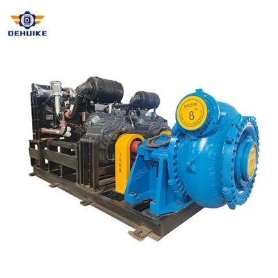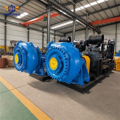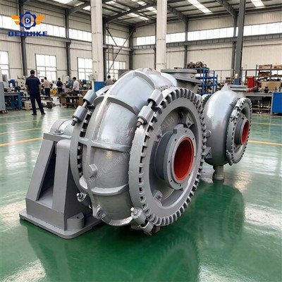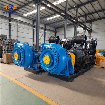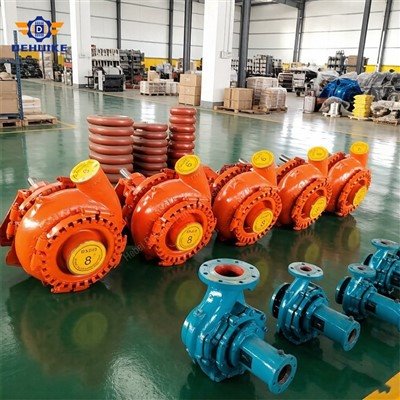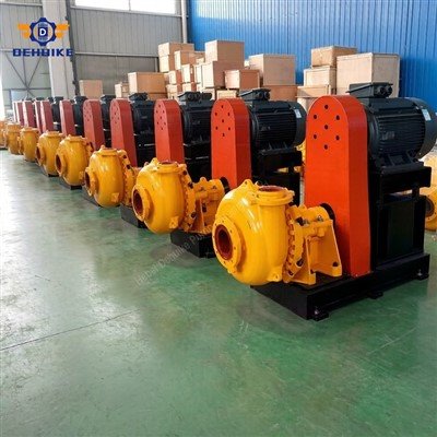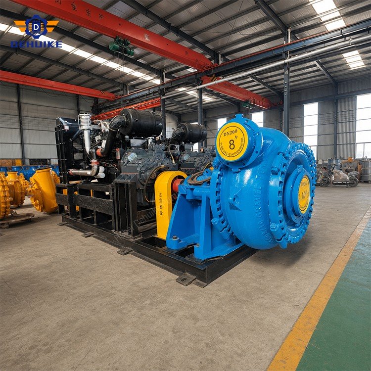
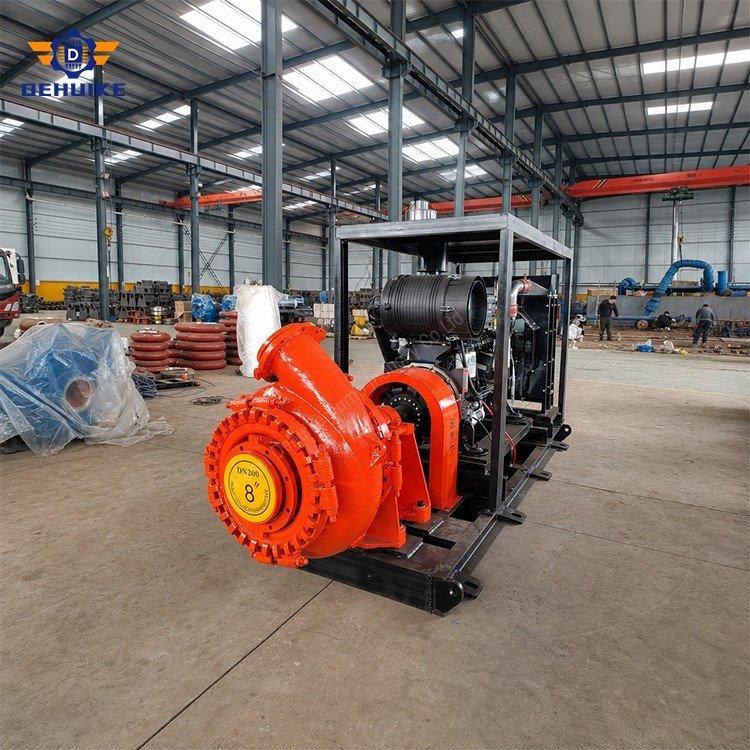
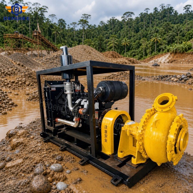
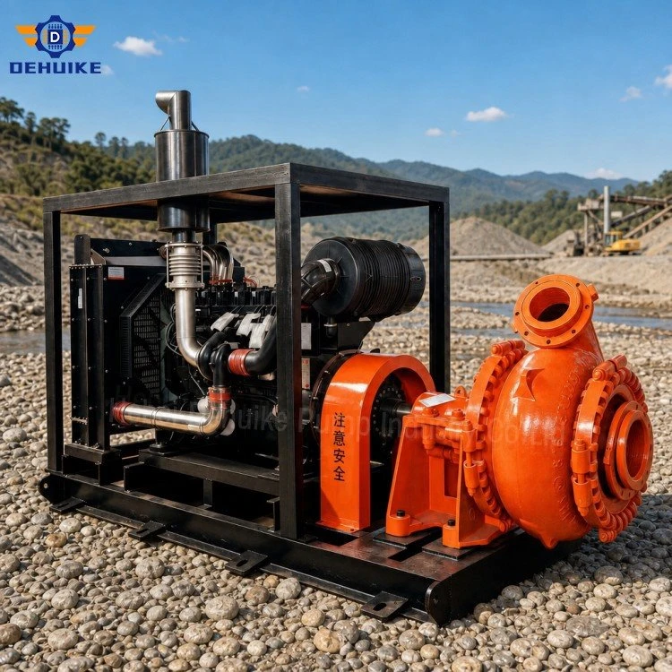
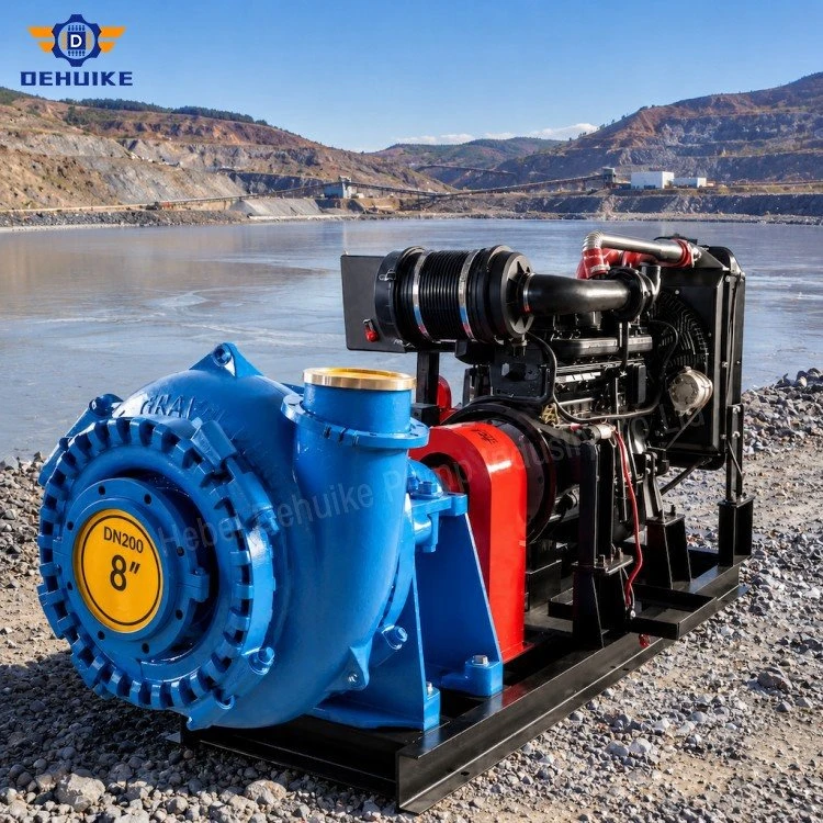
Hebei Dehuike Pump Industry Co., Ltd. is one of the most reliable manufacturers and suppliers of dredging sand pump in China. With abundant experience, we are committed to providing high quality customized pumps with competitive price. Welcome to wholesale bulk dredging sand pump for sale here from our factory. Also, pricelist is available.
Introduction | Connect Underwater Excavation To The Placement Area
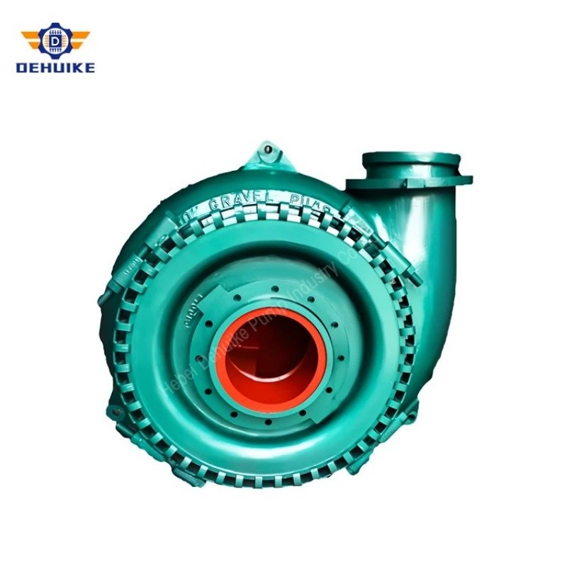
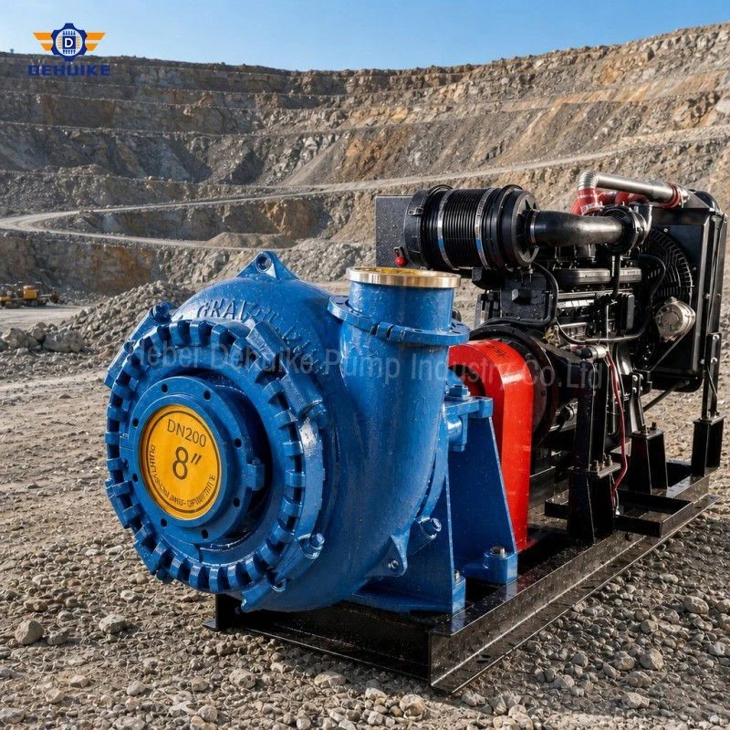
A Dredging Sand Pump moves an excavated water-sediment mixture from an underwater intake into a discharge system. In a hydraulic dredging operation, the pump works between two changing boundaries: the material being loosened at the bottom and the placement route on the discharge side. Digging depth, cut geometry, pipeline length and sediment character can all change during the same project.
The five G Series records presented here support preliminary screening for different dredging duties. A Dredging Sand Pump is not a complete dredger and its mixture capacity is not an in-situ production guarantee. Excavation head, suction line, vessel or pontoon arrangement, pipe system, booster stations and placement facility must be engineered together.
When the deposit contains shells, gravel or isolated stones, a Heavy Duty Gravel Pump may provide the coarse-solids handling class required by the project. It still needs an accepted feed envelope and debris-control plan. Dredged timber, wire, refuse and irregular rock cannot be treated as ordinary sand merely because they enter the same suction mouth.
Specifications / Technical Data | Relate Pump Coordinates To The Dredge Profile
The physical fields and hydraulic coordinates below are taken from selected G Series product data. Each capacity, head, speed, efficiency and motor entry remains an intact listed operating record. The available product data does not state dredging depth, suction-pipe diameter, slurry density, discharge distance, booster arrangement or placement elevation.
|
G Series model |
Particle reference (mm)* |
Suction size (mm) |
Discharge size (mm) |
Pump weight (kg) |
|
6/4D-G |
82 |
150 |
100 |
460 |
|
8/6E-G |
127 |
200 |
150 |
1120 |
|
10/8F-G |
178 |
250 |
200 |
2250 |
|
14/12G-G |
241 |
350 |
300 |
5400 |
|
16/14-G |
255 |
400 |
350 |
6950 |
The particle entry is a catalogue reference, not a routine dredged-feed specification. The source gives no particle shape, upper-size frequency or passage-test method. Compare the accepted feed with the dredge intake, pump, valves, flexible connections and every downstream restriction.
Build the required head from the complete dredging route. Include the elevation difference between source and placement, suction-side losses where applicable, discharge friction, fittings, floating-hose resistance, shore-pipe sections and any terminal pressure. The selected table head cannot be assigned to a project before these components are calculated.
Mixture flow includes transport water. In-situ dredging production depends on solids concentration, sediment density, excavation efficiency, swing or advance pattern, uptime and placement constraints. Keep pump cubic metres per hour separate from bank cubic metres or dry tonnes per hour, and state every conversion assumption.
The motor entry belongs to the listed catalogue point. Final power review needs slurry correction, mixture density, drive losses, service margin and all planned operating cases. Digging deeper does not justify an automatic speed increase; suction losses and solids payload must be evaluated together.
Add dredge-specific columns to the selection schedule: highest and lowest water level, maximum digging depth, suction-line geometry, discharge configurations, placement elevation, booster station status and expected density band. This converts the Dredging Sand Pump shortlist into a system review without changing the source figures.
For long projects, preserve separate calculations for initial, intermediate and final pipeline lengths. A machine that meets the short route may lose delivery after the working face moves, while one selected only for the final route may be poorly positioned at project start. Record the curve revision and assumptions for every stage.
Prepare a suction-loss budget for each planned cut depth. List intake entrance loss, suction-pipe friction, bends, flexible joints, velocity head, slurry-density assumption and available atmospheric or flooded pressure contribution. The purpose is to show where inlet margin is consumed. A deeper cut is not represented correctly by adding the same number of metres to discharge head.
For a multi-station discharge, divide the route into pressure zones. Calculate the inlet and outlet condition of the dredge pump and every booster at the same mixture flow. Check the minimum pressure needed to avoid unstable feed to the next station and the maximum pressure permitted by pipe, hose, joint and pump-casing data. Station spacing should follow these limits rather than a fixed distance rule.
Add a dredging configuration matrix beside the specification table. Useful columns include cut depth, water level, swing position, sediment layer, suction assembly, total floating line, submerged line, land line, number of boosters, terminal elevation and placement mode. Evaluate the critical combinations, not every variable independently, because the longest line may not occur with the deepest cut.
Use a production reconciliation sheet after commissioning. Compare mixture flow and density at the pump with surveyed in-situ volume and accepted placement volume over the same interval. Differences can reveal dilution, bulking, return water, bypass or measurement mismatch. Keeping these figures separate prevents the catalogue pump coordinate from being treated as a certified excavation rate.
Where multiple impeller or speed arrangements are available, require the vendor to identify which configuration generated the submitted curve. Record any trimming, clearance or speed limit that changes the available duty. A later replacement part must preserve that hydraulic identity if the original selection basis is to remain valid.
Product Detail | Follow Sediment From The Digging Face To Discharge
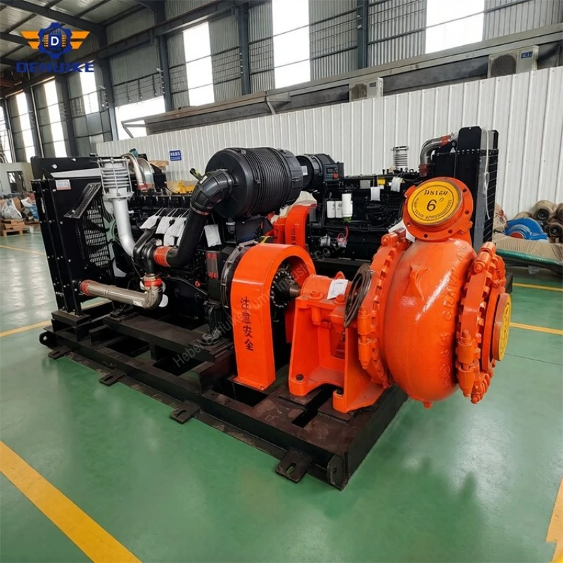
Suction performance is constrained by the pressure available to move slurry toward the pump. Greater depth, longer suction piping, bends, high velocity, air leakage and dense feed consume that margin. A Dredging Sand Pump can move more water when speed rises yet carry less useful solids if the intake and suction system are no longer balanced.
On the discharge side, steel, HDPE and flexible floating sections can impose different resistance and mechanical demands. Shore transitions, pontoon movement and anchors must be designed separately from the pump. The available product data does not define compatible dredge pipe, pressure class, cutter head or vessel arrangement.
Features / Equipment Characteristics | Operate Within The Dredging Envelope
-Characterize sediment by location and depth. Surface samples can miss buried gravel lenses, compact layers, shells or debris.
-Coordinate excavation rate with suction capacity. Overfeeding the mouth can create unstable density or blockage; underfeeding mainly circulates water.
-Track floating and shore pipeline changes. Added hose, bends and elevation move the duty even when the Dredging Sand Pump speed is unchanged.
-Define foreign-object controls. A Heavy Duty Gravel Pump is not a shredder for rope, metal, timber or construction waste.
There is no universal dredging velocity or solids percentage suitable for every route. Transport stability depends on particle grading, solids density, concentration, pipe diameter and layout. The project calculation should identify normal, reduced-production and clearing conditions without turning one handbook value into a product guarantee.
Our Advantages | Evaluate Useful Dredged Volume Across The Full Campaign
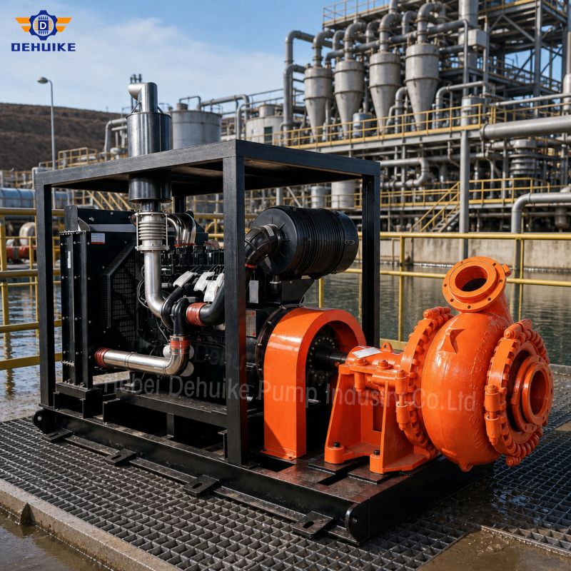
A five-model G Series shortlist lets the designer examine several hydraulic scales before committing to a dredge arrangement. The best option is not necessarily the largest pump. A larger unit can increase dilution, suction difficulty, fuel demand and pipeline stress if excavation and placement cannot use its mixture capacity.
For a Dredging Sand Pump comparison, measure useful in-situ material moved to the approved destination per operating period. Include water volume, downtime, relocation, pipeline handling, blockage clearing, booster operation and wear parts. Pump efficiency at one coordinate is only one component of campaign cost.
Existing dredging records can improve replacement selection. Compare depth, density, speed, suction vacuum where measured, discharge pressure, pipe length and production before blaming the pump. A new Heavy Duty Gravel Pump cannot correct an undersized cutter, leaking suction joint or restricted placement outlet.
Production Process And Quality Assurance | Define The Dredge-pump Package Boundary
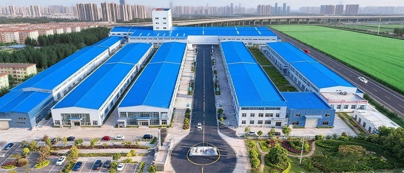
Production process: freeze interfaces before package assembly
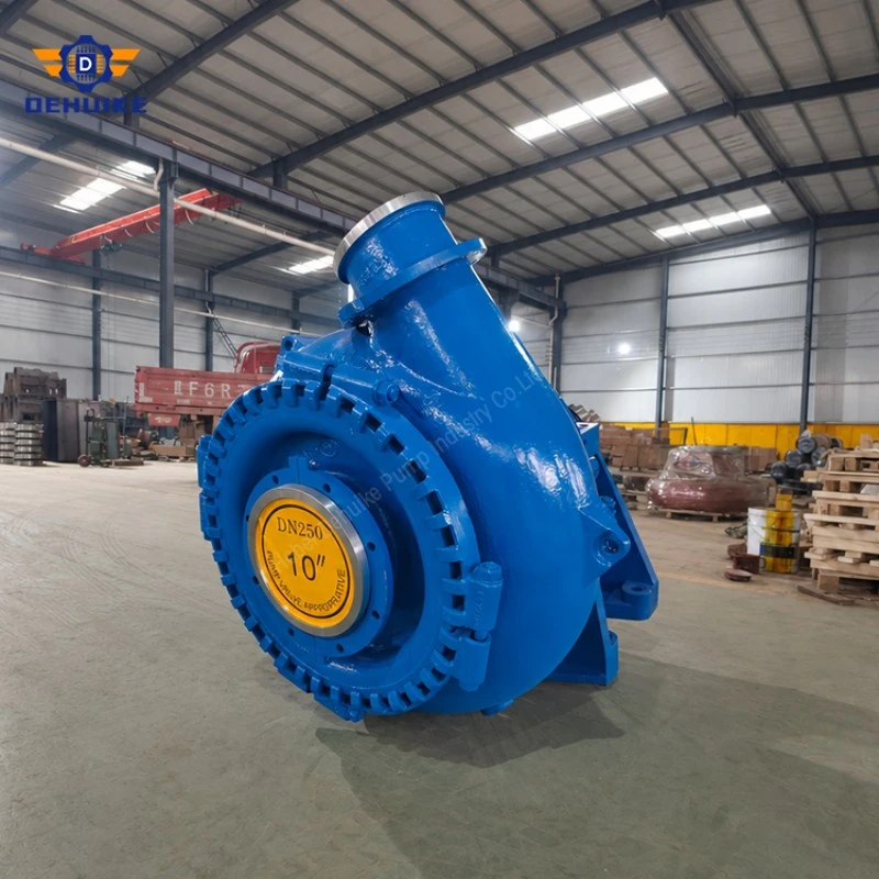
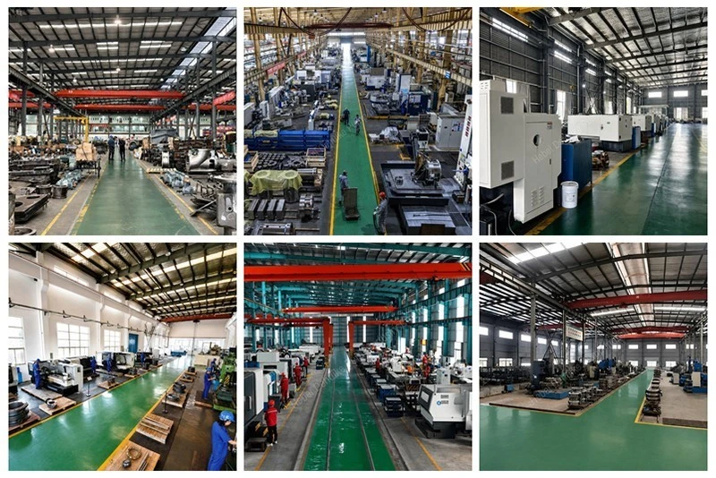
Approve the pump model, impeller configuration, wetted materials, seal, driver and connection drawing before manufacture. If a gearbox, coupling, guard, base or monitoring item is included, identify its interface with the dredge structure. Machining and assembly checks should preserve the released hydraulic and mechanical configuration. These are procurement requirements, not evidence of an undocumented factory routine.
The supplied Dredging Sand Pump and loose accessories should remain traceable through packing. Protect open nozzles and machined interfaces for transport to the vessel or site. Lifting points and centre of gravity require an approved package drawing; bare-pump mass in the available product data is only a planning input.
Quality assurance: separate pump acceptance from dredging production
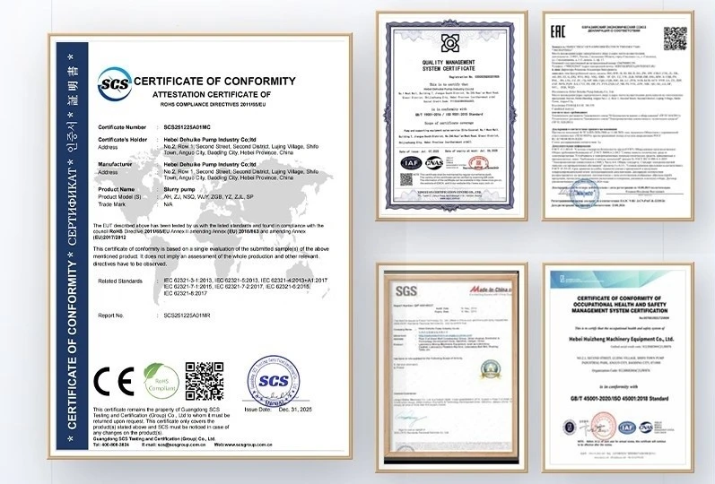
Material documents, dimensional checks, balancing records and hydraulic tests address different claims. A defined clean-water test can verify an agreed reference condition, but it cannot reproduce sediment excavation, suction aeration, pipeline movement or site production.
The available product data provides no pressure class, test standard, marine classification, vibration limit, dredger integration certificate or production warranty. Specify any mandatory evidence contractually. Do not describe an individual pump test as acceptance of the complete dredging system.
Applications | Adapt The Pump Arrangement To The Dredging Method
A Dredging Sand Pump can be considered for permitted cutter-suction work, barge loading, channel maintenance, reservoir sediment transfer and selected beach or upland placement systems. The examples below illustrate engineering questions rather than documented projects or regulatory approvals.
Compact dredge with a shorter line
The 6/4D-G and 8/6E-G reference points are 158 m3/h at 50.5 m and 410 m3/h at 43 m. These coordinates can support preliminary review of smaller packages, but the suction arrangement and driver must suit the vessel or pontoon. High listed speed does not prove high solids payload.
Intermediate shore-placement route
The selected 10/8F-G point gives 670 m3/h at 42 m. Map the working face, floating line, shore transition and placement elevation before judging suitability. The 220 kW motor entry still needs slurry and drive verification.
Large-volume cutter or booster duty
The 14/12G-G and 16/14-G rows list 2320 m3/h at 56.5 m and 2249 m3/h at 40.4 m. They represent different head demands at similar flow scale. A Heavy Duty Gravel Pump used as a dredge or booster unit must be matched to the same pipeline capacity and coordinated start-stop sequence.
Placement route that lengthens during the contract
As excavation advances, extra pipe and fittings raise resistance. Calculate stage-by-stage intersections and decide whether speed adjustment, pipe change or a booster is appropriate. A late booster must also be checked against pipe pressure, station spacing and the consequence of either pump stopping.
Deepening cut with unchanged placement point
When the ladder or suction head works lower, available inlet margin can become the controlling constraint before discharge head does. Compare production at each depth band using the accepted suction-loss budget. If solids payload falls while water flow rises, review excavation feed and inlet velocity rather than assuming that more speed is the answer.
Floating line exposed to current and vessel traffic
The hydraulic length may remain constant while hose curvature and mechanical restraint change. Define operating positions, anchor pattern, allowable bend radius and navigation controls. Mechanical movement belongs to the pipeline design, but its changing geometry should also be reflected in the resistance cases used to assess pump duty.
Upland placement with changing pond level
A confined placement area can develop higher discharge elevation or backpressure as the campaign progresses. Include the initial and maximum expected terminal condition. Water-management restrictions may also limit permissible mixture flow independently of pump capability, so placement acceptance must be part of the operating plan.
Temporary bypass around a booster station
Maintenance may require a shorter or altered route while one station is isolated. Model the bypass separately and define the permitted pump settings. The remaining unit must not be driven outside its approved region, and the bypass pipe and joints must be checked for the resulting pressure distribution.
Our Service, Experience And Markets | Submit A Dredging System Data Package
For a Dredging Sand Pump enquiry, submit all discharge configurations: floating line, submerged line, shore pipe, terminal elevation and placement backpressure. Mark pipe diameters, materials, joints, bends and planned extensions. Separate measured conditions from assumptions.
Request the selected curves, suction review, corrected power, material schedule, package drawing, inspection scope, commissioning support and initial spares. Confirm commercial availability at the destination. The available product data contains no dredging references, fleet integration record, country network or response-time promise, so those claims are omitted.
Installation, Operation And Maintenance | Manage Movement, Suction And Settled Material
Commission the Dredging Sand Pump with baseline speed, power, suction and discharge readings before increasing excavation feed. Record depth, density and pipeline arrangement with every test. A water-rich start-up point cannot be used as the final solids-production reference.
During dredging, diagnose falling production from a complete data set. A deeper cut, air leakage, worn pump, changed sediment, longer line or restricted placement point can create different evidence. Increasing speed without identifying the cause can reduce solids payload and increase water handling.
Plan shutdown and emergency clearing for every low section of line. Before opening a Heavy Duty Gravel Pump, isolate the driver, prevent remote start, relieve pressure and secure moving equipment. Restart only after the approved procedure confirms the suction and discharge paths are ready.
Faq | Specify A Dredging Sand Pump From The Full Project Duty
1. Is a dredging sand pump a complete dredger?
No. It is one component of a hydraulic dredging system. Excavation equipment, suction pipe, vessel or pontoon, drive, discharge line, booster stations, placement facility and controls are separate unless explicitly included.
2. Can pump flow be quoted as dredging production?
No. Pump flow is mixture volume. In-situ production also depends on solids concentration, sediment density, excavation efficiency, downtime, placement limits and the reporting basis used by the project.
3. Why does digging depth affect selection?
Depth changes the suction geometry and available inlet conditions. Greater velocity is not automatically beneficial. Suction losses, air entry, density and solids payload must be optimized for each depth range.
4. When is a booster pump needed?
A booster may be considered when discharge distance, elevation and friction exceed the practical duty of one station. Series operation requires pressure, matching-flow, control, start-up and shutdown analysis for the complete line.
5. What sediment data should be supplied?
Provide grading by location and depth, density, shells or gravel, compactness where relevant, chemistry and debris risk. Surface samples alone may not represent deeper strata encountered during the contract.
6. Does a larger pump always increase dredging output?
No. Excavation feed, suction capacity, pipeline transport and placement can constrain production. A larger unit may move more water without increasing useful solids if the rest of the system is not matched.
7. What pipeline information is required?
Submit each pipe section's length, diameter, material, elevation, fittings and operating configuration. Include floating, submerged and shore sections, planned extensions and terminal conditions.
8. What should a technical offer contain?
Request marked curves, slurry corrections, suction data, motor basis, materials, seal arrangement, package drawing, tests, spares, operating limits and exclusions. Production assumptions should be documented separately.

Request A Dredging-duty Review
For a Dredging Sand Pump proposal, send the sediment profile, digging-depth range, suction arrangement and every discharge route. If a Heavy Duty Gravel Pump is proposed, require the selected curve, corrected power, accepted feed definition, package pressure limits and supply boundary before approval.
Hot Tags: dredging sand pump, China dredging sand pump manufacturers, suppliers, factory