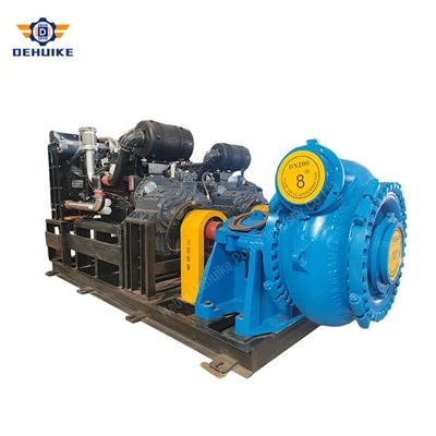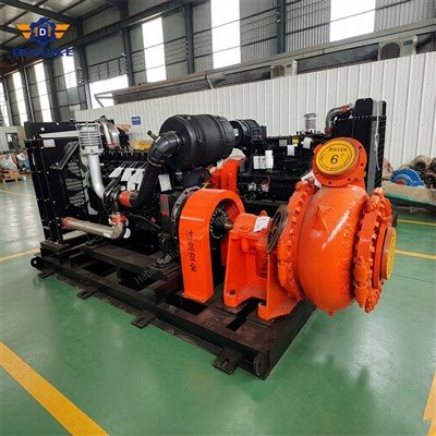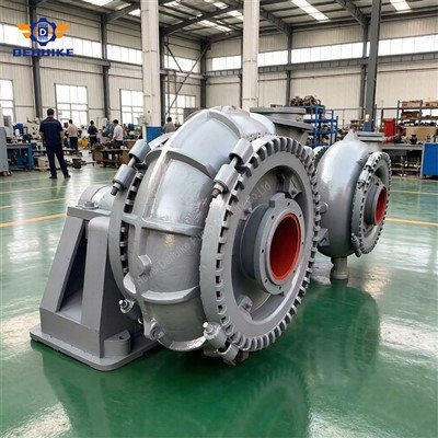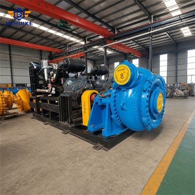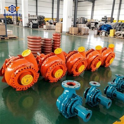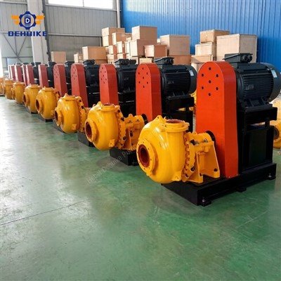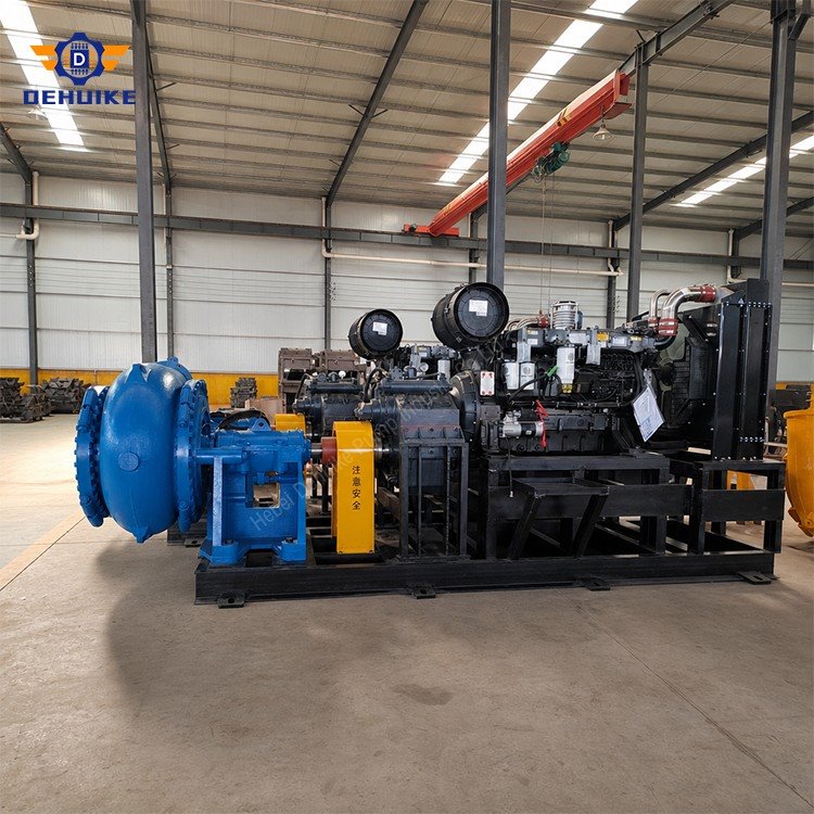
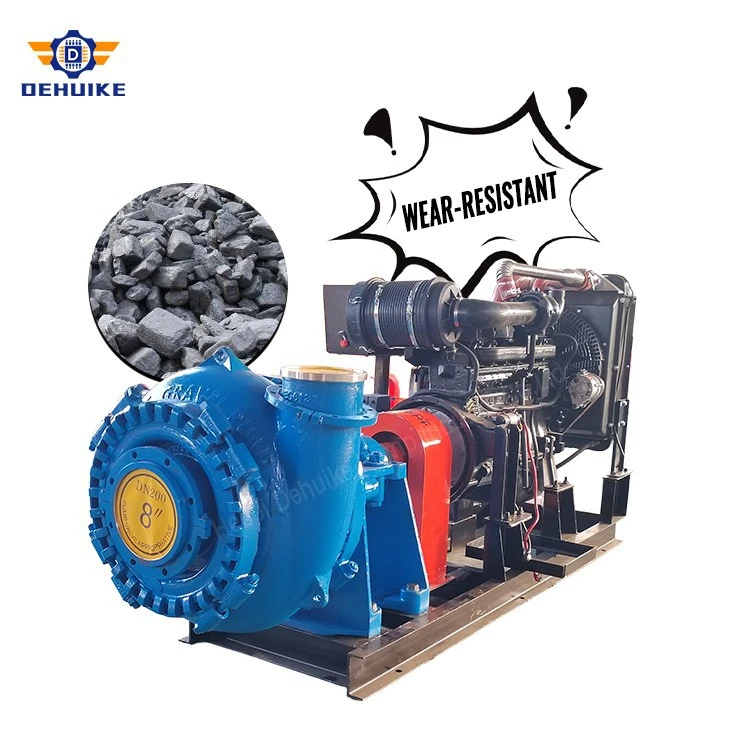
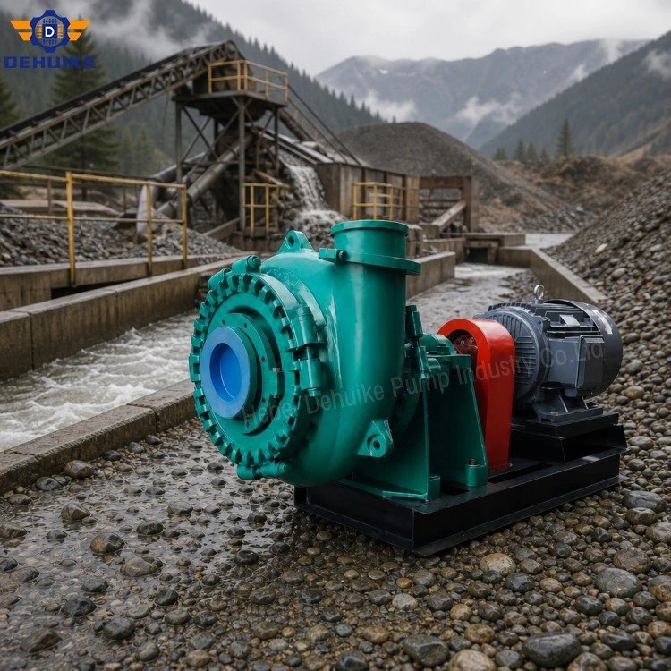
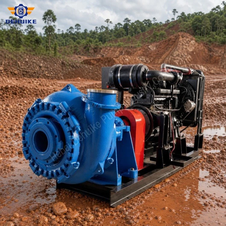
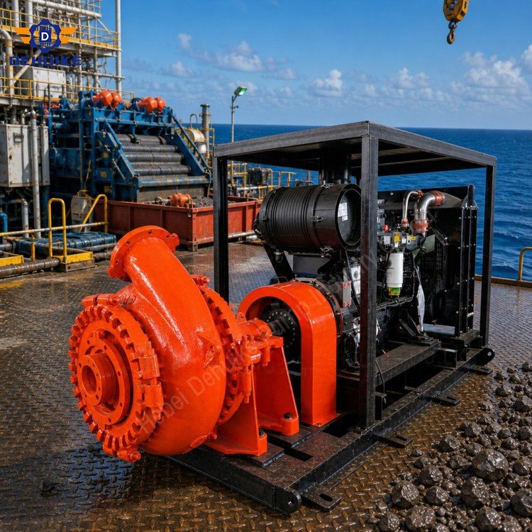
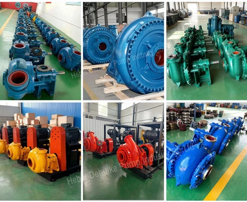
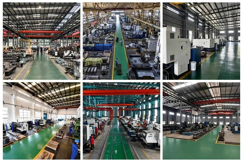
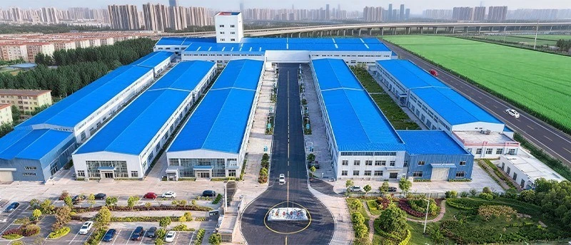
Hebei Dehuike Pump Industry Co., Ltd. is one of the most reliable manufacturers and suppliers of centrifugal gravel pump in China. With abundant experience, we are committed to providing high quality customized pumps with competitive price. Welcome to wholesale bulk centrifugal gravel pump for sale here from our factory. Also, pricelist is available.
Introduction | Select The Centrifugal Machine Together With Its System
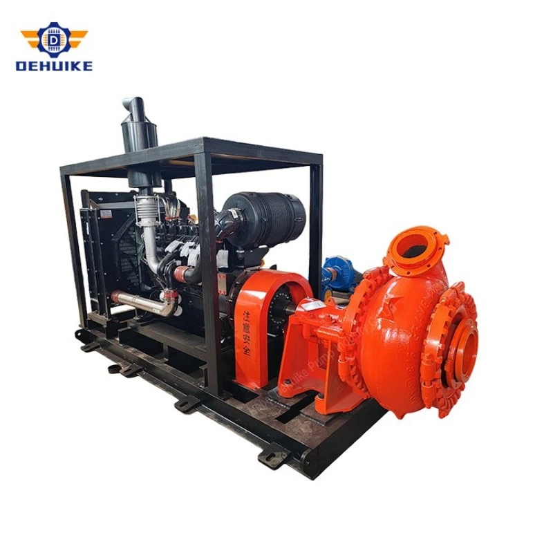
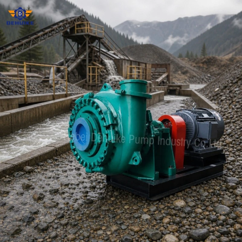
A Centrifugal Gravel Pump uses a rotating impeller to add energy continuously to a liquid-solids mixture. The casing collects the outgoing flow and leads it into the discharge pipe. This principle allows large mixture volumes to be transferred without a reciprocating pumping cycle, but the delivered flow is not fixed independently of the connected system.
The actual duty develops where the pump characteristic meets the resistance imposed by elevation, pipe friction, fittings and discharge conditions. A Centrifugal Gravel Pump must therefore be selected from both sides of that intersection. Choosing only a catalogue capacity can produce a different field result when pipeline length, liquid level or valve position changes.
The G Series records used below provide five traceable operating points for coarse-solids discussion. They do not describe the complete curves. A Heavy Duty Gravel Pump still needs manufacturer curve data, slurry correction and an inlet-condition review before the motor and operating range can be approved.
Specifications / Technical Data | Read One Point As Part Of A Curve
Each selected row below is an selected G Series product data. The tables preserve the association among capacity, total head, rotational speed, efficiency and motor listing. These coordinates are useful anchors, but one coordinate cannot show shut-off behaviour, the efficiency band, power variation or required suction performance across the full operating range.
|
G Series model |
Particle field (mm)* |
Suction opening (mm) |
Discharge opening (mm) |
Pump-only mass (kg) |
|
6/4D-G |
82 |
150 |
100 |
460 |
|
8/6E-G |
127 |
200 |
150 |
1120 |
|
10/8F-G |
178 |
250 |
200 |
2250 |
|
14/12G-G |
241 |
350 |
300 |
5400 |
|
16/14-G |
255 |
400 |
350 |
6950 |
|
G Series model |
Capacity (m3/h) |
Total head (m) |
Rotational speed (r/min) |
Point efficiency (%) |
Motor record (kW) |
|
6/4D-G |
205 |
18 |
900 |
58 |
37 |
|
8/6E-G |
390 |
12.5 |
900 |
58.5 |
45 |
|
10/8F-G |
695 |
21.2 |
730 |
62.2 |
110 |
|
14/12G-G |
2320 |
56.5 |
700 |
64.2 |
900 |
|
16/14-G |
1830 |
13.8 |
300 |
67.6 |
220 |
The particle field remains a technical-data reference rather than an approved everyday feed limit. Shape, frequency and simultaneous entry are unspecified. It cannot be used to infer impeller geometry or the free passage of every downstream fitting.
For curve review, ask for H-Q, efficiency, input power and NPSHR information at the proposed speed. KSB's centrifugal-pump lexicon describes these as characteristic-curve parameters plotted against flow. The selected Centrifugal Gravel Pump should also be checked for the supplier's permitted continuous range; that range is not present in the available product data.
A separate calculation must translate water-based performance to the proposed mixture where correction is required. Record solids density, concentration basis, grading and carrier properties. The motor record in this table is not a substitute for corrected absorbed power, drive losses and the specified service margin.
Treat the five rows as navigation marks rather than a model ranking. First locate the project duty on the relevant model chart. Then examine nearby capacity on both sides, the associated efficiency contour, input curve and suction requirement. This reveals whether normal process variation remains inside a usable region or crosses a vendor limit. A selection sheet should preserve the curve revision and impeller configuration used for that review.
The capacity coordinate answers how much mixture moves under the stated reference condition. The head coordinate answers how much energy per unit weight is added. Rotational speed identifies the curve family, while point efficiency helps describe hydraulic conversion at that coordinate. These meanings must remain separate. Multiplying capacity by slurry density does not create another valid curve point, and a larger motor does not force the machine to deliver the printed capacity.
For a procurement schedule, add columns that are deliberately absent from the available product data: curve number, impeller identification, test-fluid basis, NPSHR at duty, corrected slurry head, corrected absorbed power, operating-zone status and driver margin. Mark each as vendor-supplied or project-calculated. This creates an auditable bridge from catalogue data to the final Centrifugal Gravel Pump selection without altering the source figures.
When two candidate sizes can reach the required coordinate, compare more than peak efficiency. Review inlet margin, expected process swing, speed, solids passage, driver loading and the consequence of a future line extension. The preferred option is the one with a defensible working envelope for the defined system, not necessarily the machine with the highest numerical value in one column.
Include a deviation register with the technical offer. It should identify every difference between the enquiry basis and the vendor calculation, such as assumed pipe roughness, omitted fittings, revised elevation, concentration interpretation or test speed. Closing those deviations before approval is essential because a small undocumented assumption can move the calculated intersection and alter the selected driver.
Archive the final marked chart beside the equipment record. Operators can then compare future measurements with the selection basis after valves, lines or process levels change. Without that retained reference, troubleshooting often falls back to nameplate capacity, which is not evidence of the current system intersection.
Product Detail | Trace Energy From Shaft To Slurry
Drive torque reaches the pump shaft and turns the impeller. Liquid and entrained solids enter near the impeller eye, pass through the rotating passages and leave with greater velocity and pressure energy. The casing decelerates and redirects the mixture toward the outlet. The result is a continuous conversion of mechanical input into hydraulic energy, with unavoidable losses in the rotating and stationary flow paths.
Coarse solids complicate this process. Their motion can lag the carrier liquid, and collisions with metal surfaces consume energy and cause wear. Concentration and particle grading can alter the head, efficiency and power relationship from a water test. The Centrifugal Gravel Pump is therefore a two-phase application even though its basic machine principle is centrifugal.
The parameter available product data does not identify impeller vane count, casing profile, internal clearances or NPSHR. Those design and curve details must come from the selected supplier. The product title should not be used to infer self-priming ability, dry-running capability or a particular seal arrangement.
Features / Equipment Characteristics | Understand The Operating-point Intersection
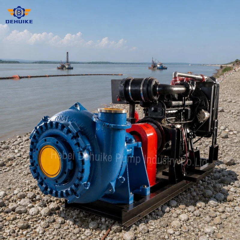
The flow delivered by a centrifugal pump settles where its H-Q characteristic intersects the system characteristic. Increasing static lift or friction raises the system demand and moves the working point. Reducing resistance moves it elsewhere. This explains why two sites using the same model and speed can report different capacity.
-Build the system curve from elevation and hydraulic losses instead of assigning the catalogue point directly to the site.
-Check all expected configurations, including added pipe, a changing liquid level, alternate discharge routes and partially closed valves.
-Use variable speed only within the approved range and recalculate power, solids transport and suction conditions for the revised point.
-Keep the Heavy Duty Gravel Pump away from prolonged operation in a region the manufacturer does not approve for continuous service.
The operating point can shift during the life of the installation as a line becomes restricted, wears, is extended or changes elevation. A Centrifugal Gravel Pump selection should document the initial design case and the credible boundary cases so operators can recognise when the circuit has moved.
Our Advantages | Use Curve-based Decisions Instead Of Oversized Assumptions
A Centrifugal Gravel Pump can also be integrated with control methods such as approved speed adjustment or system-side regulation, but every method moves or changes the operating point. The control philosophy should be evaluated for slurry transport, absorbed power and wear rather than for liquid flow alone.
For commercial comparison, ask each supplier to mark the proposed point on the submitted curve and state the slurry assumptions, speed, driver basis and operating limits. A Heavy Duty Gravel Pump bid that provides only one performance line gives the buyer less evidence for future changes and troubleshooting.
Production Process And Quality Assurance | Preserve Hydraulic Geometry And Curve Identity
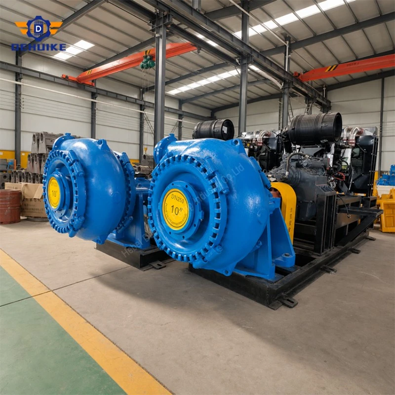
The purchase release should identify model, impeller configuration, nominal speed, direction of rotation and the drawing revision that defines the hydraulic assembly. Machining and assembly checks should preserve interfaces and clearances that influence rotation and internal geometry.
A change in impeller, casing or internal clearance can affect the relationship represented by the curve. Replacement parts should therefore remain traceable to the approved Centrifugal Gravel Pump configuration. Similar fit alone does not prove equivalent hydraulic behaviour or balance.
Quality assurance: link test data to the submitted curve
If hydraulic testing is contractual, the report should state the test liquid, speed, impeller condition, measured flow, head and input basis, together with agreed tolerances. Clean-water verification does not replicate every gravel slurry, but it can confirm the specified reference configuration when the procedure is defined.
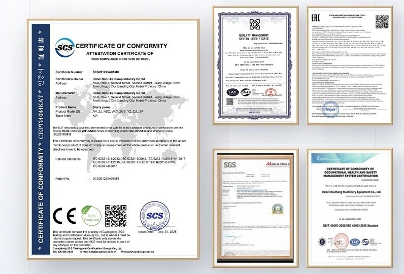
The available product data provides no test standard, curve tolerance, NPSHR acceptance, balancing grade or guaranteed operating range. Place any required values in the purchase documents. Do not advertise a test or certification solely because the page explains how centrifugal pumps are assessed.
Applications | Match The Curve To The Process Rather Than The Industry Label
A Centrifugal Gravel Pump can be considered for suitable aggregate recovery, dredging transport, quarry transfer and coarse mineral slurry systems. Application names are not selection data. The following examples show how distinct hydraulic coordinates change the engineering question; they are not customer installations or guaranteed production cases.
Lower-capacity process transfer
The chosen 6/4D-G point is 205 m3/h at 18 m and 900 r/min, while the 8/6E-G point is 390 m3/h at 12.5 m at the same nominal speed. The shared speed does not make their curves interchangeable. Review each model against the actual resistance and inlet condition.
Intermediate gravel circuit
The 10/8F-G record gives 695 m3/h at 21.2 m and 730 r/min. This coordinate can begin discussion of a medium-duty system, but the rest of the curve is needed before predicting response to throttling, pipe extension or speed control.
Larger pipeline systems
The selected 14/12G-G point is 2320 m3/h at 56.5 m, whereas 16/14-G is 1830 m3/h at 13.8 m. The larger model is not automatically the higher-head choice. For either Heavy Duty Gravel Pump, the system curve decides where the machine will actually operate.
Variable-elevation loading cycle
A loading sump may begin full and finish near its low-level cutoff. Static lift and inlet conditions change during the cycle, so one snapshot does not describe the complete run. Plot the high- and low-level cases, then verify the proposed pump's capacity, power and suction margin for both. Control logic should prevent operation outside the approved boundary as the source level falls.
Pipeline extension during site development
Quarry and dredging lines are often extended as the working face moves. Every added section and fitting changes resistance. Estimate the initial, intermediate and ultimate routes before choosing equipment. A model that suits the first stage may lose capacity later, while a machine chosen only for the final route may be poorly positioned during early operation.
Two discharge destinations
A circuit that alternates between a nearby screen and a distant stockpile has two system characteristics. The valve arrangement selects the route, but it does not make the hydraulic demands identical. Mark both intersections on the supplier curves and confirm driver loading, transport condition and the control sequence for route changeover.
Booster-pump assessment
For very long transport, adding a second centrifugal stage is a system decision rather than an automatic remedy. Review pressure distribution, start-up sequence, matching capacity, communication between stations and the effect of one unit stopping. The available product data contains no series-operation pressure limit, so a booster arrangement requires separate engineering and approved equipment data.
Our Service, Experience And Markets | Supply The Data Needed To Construct The System Curve
Provide normal, minimum and maximum mixture delivery, source and destination levels, pipeline lengths, internal diameters, materials, fittings and discharge conditions. Identify configurations that change during operation. A profile drawing is preferable to a total length because elevation and local losses need separate interpretation.
Add slurry density, concentration with measurement basis, particle grading, temperature and chemistry. For a Centrifugal Gravel Pump replacement, include the existing speed, measured suction and discharge pressures, motor load and any observed changes after pipe modifications. These records help distinguish pump wear from a changed system curve.
Ask the supplier for a marked performance curve, corrected power basis, NPSHR data where applicable, driver selection and stated operating envelope. Confirm which engineering and commissioning services are commercially included. The available product data does not establish project experience, country coverage or service response commitments.
Installation, Operation And Maintenance | Keep The Real Operating Point Visible
Install pressure measurement locations and flow indication where justified by project criticality. Their purpose is not decorative instrumentation: together with speed and motor load, they help estimate whether the Centrifugal Gravel Pump remains near the expected duty or has shifted because of system change.
Commission against the approved test plan. Confirm rotation, speed, valve positions, suction supply and initial readings before introducing the full solids duty. Compare measured conditions with the submitted curve using the supplier's correction basis rather than treating a water curve as a direct slurry guarantee.
If capacity declines, compare pressure, flow, speed, power and slurry data before changing control settings. A rising system resistance, air entry, altered concentration or internal wear can produce different evidence. Blindly accelerating a Heavy Duty Gravel Pump may raise power and wear without correcting the actual cause.
After maintenance, record replacement-part identity and restored clearances, then establish a new baseline. Isolation, pressure release, pipe restraint and guard restoration remain mandatory. Operating-point analysis never replaces the site's mechanical and electrical safety procedure.
Faq | Select A Centrifugal Gravel Pump From Hydraulic Evidence
1. What makes a gravel pump centrifugal?
A rotating impeller continuously transfers mechanical energy to the slurry. The casing then directs the energized mixture into the discharge system. Flow is determined by the interaction between pump characteristics and system resistance.
2. Is the catalogue flow guaranteed at every installation?
No. A catalogue coordinate belongs to stated conditions. The field operating point changes with elevation, friction, valves, speed, slurry properties and suction conditions. Submit the full system for selection.
3. What is the operating point?
It is the intersection of the pump H-Q characteristic and the system characteristic. If either curve changes, the intersection moves, so the delivered capacity and head can change without replacing the pump.
4. Why is a full curve needed instead of one table row?
A full submission shows how head, efficiency, power and required suction performance vary with flow. One row cannot show the approved continuous range or the response to a changed pipeline.
5. Does a water curve apply directly to gravel slurry?
Not automatically. Solids and carrier properties can alter head, efficiency and absorbed power. Request the supplier's correction method and state density, concentration, grading and liquid properties.
6. Can speed be increased to obtain more flow?
Only after recalculating the revised duty, power, suction requirement, solids transport and equipment limits. Variable speed moves the pump characteristic and the operating point; it is not an unrestricted production control.
7. What suction information should be supplied?
Provide source liquid level range, pump elevation, suction length and diameter, fittings, temperature, atmospheric conditions where relevant and anticipated inlet losses. Ask for the required suction performance of the selected pump.
8. How should two centrifugal gravel-pump offers be compared?
Compare marked duty points, full curves, slurry corrections, motor basis, NPSHR information, operating envelope, materials and supply scope. Nominal connection size or motor power alone is not a technical comparison.

Request A Curve-based Selection Review
For a Centrifugal Gravel Pump proposal, send the full system profile and slurry definition. If a Heavy Duty Gravel Pump is recommended, require the selected curve, corrected power, suction data, driver basis and operating limits before order release.
Hot Tags: centrifugal gravel pump, China centrifugal gravel pump manufacturers, suppliers, factory