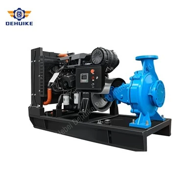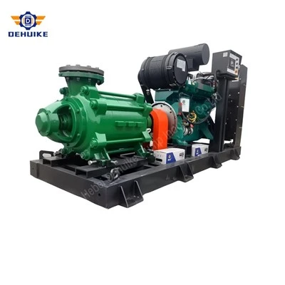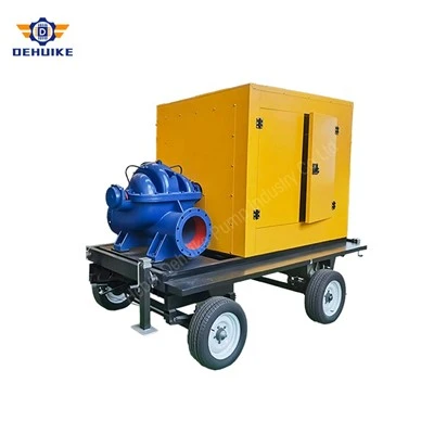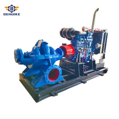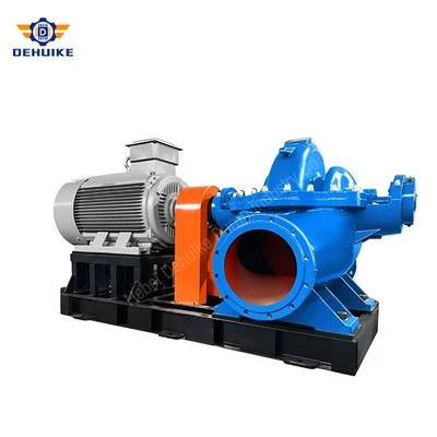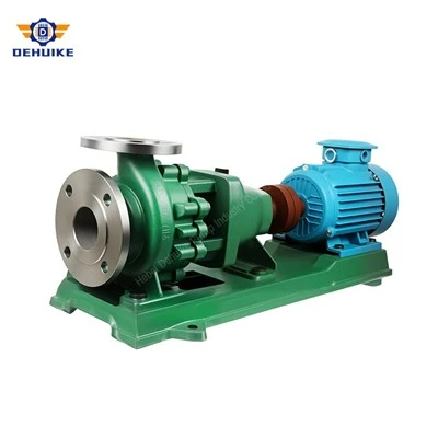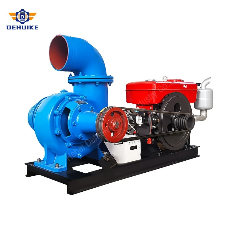
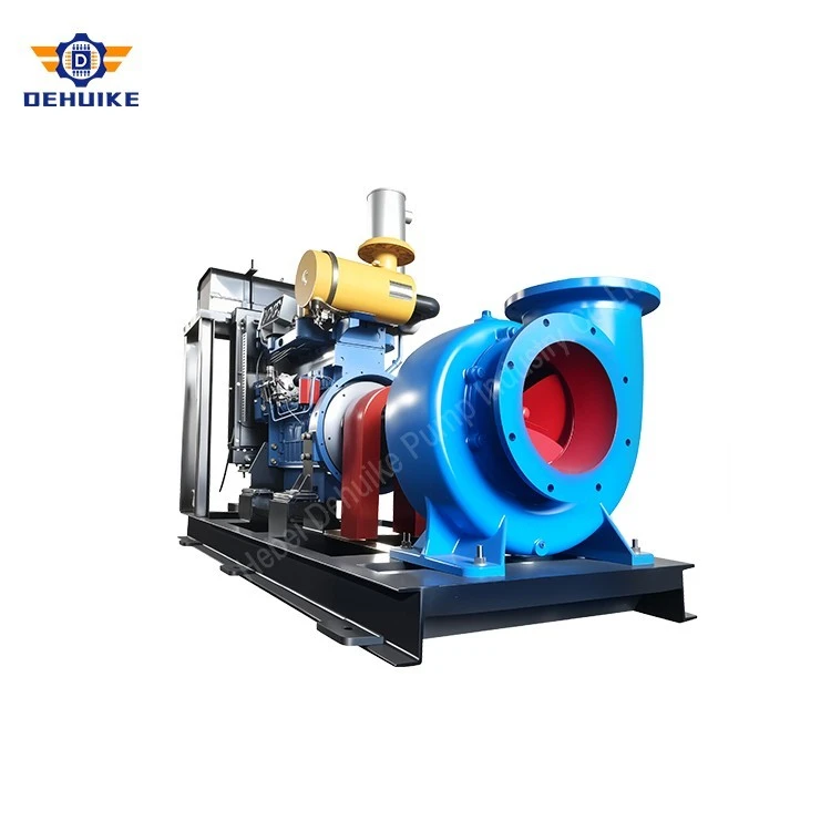
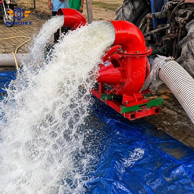
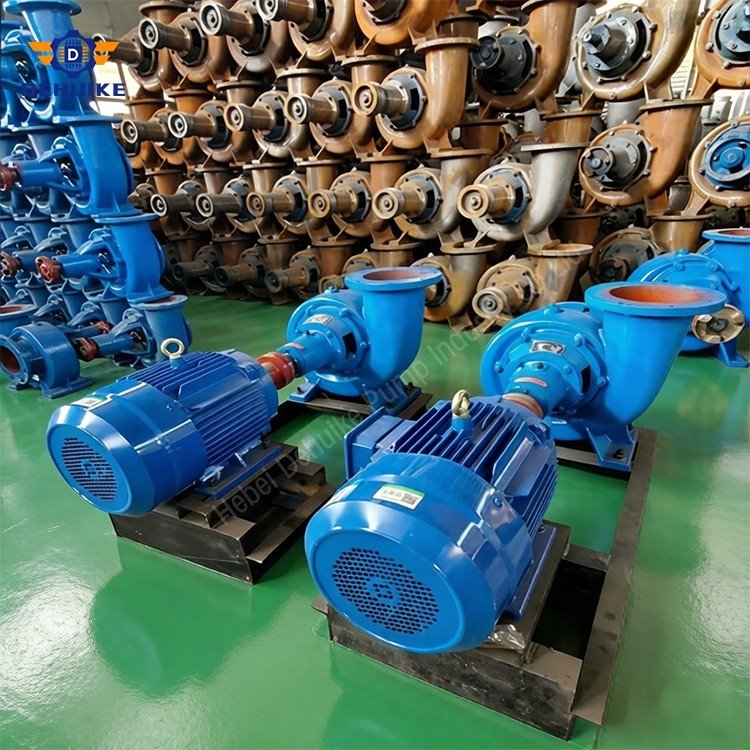
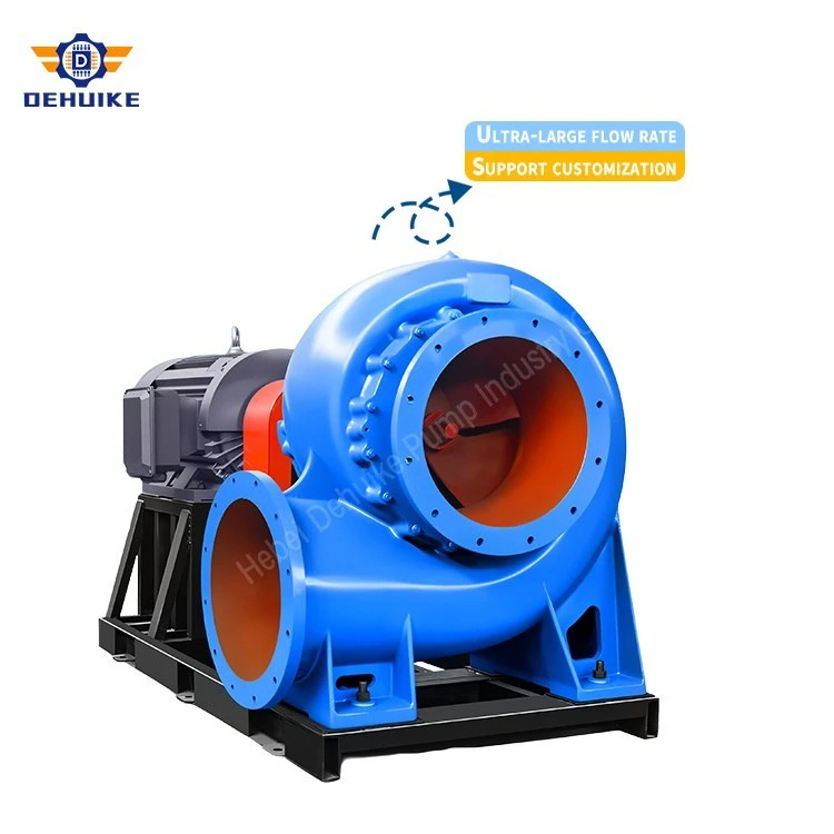
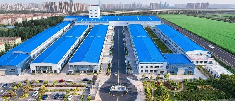
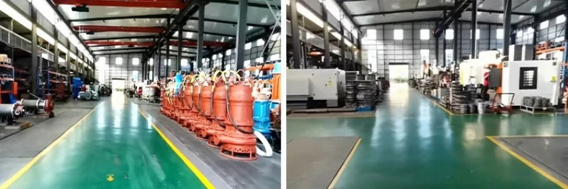
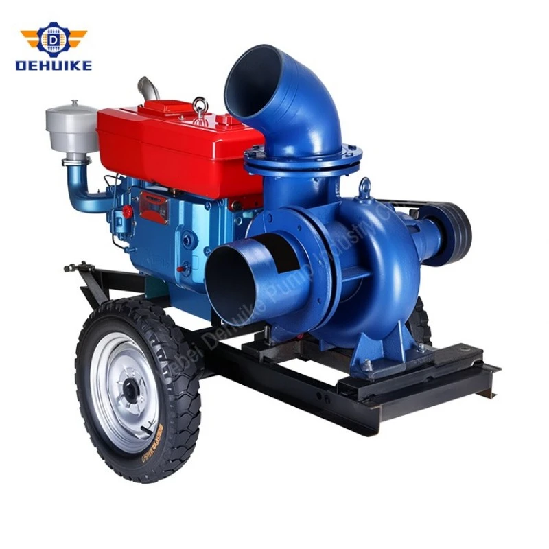
Hebei Dehuike Pump Industry Co., Ltd. is one of the most reliable manufacturers and suppliers of axial mixed flow pump in China. With abundant experience, we are committed to providing high quality customized pumps with competitive price. Welcome to wholesale bulk axial mixed flow pump for sale here from our factory. Also, pricelist is available.
What the Runner Does With the Water
The familiar volute machine drives water outward from a narrow wheel and converts the resulting speed into pressure. A propeller does the opposite: it pushes water along the shaft with barely any pressure gain, which suits a fixed low lift and nothing else.
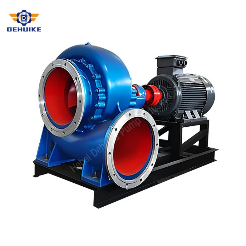
The semi-axial wheel occupies the middle. Its blades are set at an angle, so water leaves the wheel moving outward and forward at once. A row of fixed vanes behind the runner takes the swirl out of that flow and converts it into pressure. The outcome is propeller-scale volume at several times propeller lift, and no volute is required.
That geometry can be read from the pipe. The outlet is normally a short, fat main between DN600 and DN900 for a flow near 1 m3/s. A machine that makes volume instead of pressure has none of it to waste on friction.
The Two Neighbours, and Why They Lose
A radial machine of the same bore would need a much taller head to reach its efficient band. Forced down to 3.5 m, it runs past the end of its curve, draws more power than the duty requires and passes the flow through passages that were never sized for it. The station would end up with a 90 kW motor doing work that 42 kW can cover.
The propeller fails the other way. Its power climbs steeply as the head falls, since it keeps accelerating water it cannot lift. On a tidal outfall the head can halve within a tide, and a driver matched to the design point can be into overload before anyone walks down to the panel. The semi-axial wheel flattens that curve, which is why it survives a site where the water level moves.
Four Numbers That Fix the Duty
Hydraulic power comes first. Density times gravity times flow times head: 1000 x 9.81 x 1.0 x 3.5 gives 34.3 kW handed to the water. Divide by the pump's efficiency at that point and the shaft load appears. At 0.82 the figure is 41.8 kW; at 0.70 it is 49.0 kW. The difference is a 45 kW motor against a 55 kW one, plus a heavier starter and a bigger annual bill. Efficiency here is a purchasing decision, not a footnote.
Pipe bore comes second. A DN700 main has roughly 0.385 m2 of area, so 1 m3/s travels at 2.6 m/s. A DN500 main has 0.196 m2 and the same flow reaches 5.1 m/s, which turns a short rising main into a friction problem and pulls the duty point off the curve. Between the two, the wider pipe usually pays for itself in motor size alone.
Intake area comes third. A bellmouth of 1.2 m diameter presents about 1.13 m2, so approach velocity is 0.88 m/s. Hold that near or under 1 m/s and the basin stays calm at low water; push it past 1.5 and the surface starts to dimple.
Submergence comes fourth. Measure from low water to the bellmouth lip. One and a half diameters is the usual floor, so 1.8 m under a 1.2 m bellmouth, and more where the approach channel is short or the basin narrow. A station designed to the minimum will run dry once a year and lose suction at the worst moment.
Speed, and the Cube in the Affinity Law
Flow moves with speed, head with its square, power with its cube. One law covers most of what a variable-speed station does.
Table 1 Computed points for one runner at three speeds
|
Speed (r/min) |
Flow (m3/h) |
Head (m) |
Shaft load (kW) |
Reading |
|
820 |
3,012 |
2.45 |
24.5 |
Dry-season running |
|
980 |
3,600 |
3.50 |
41.8 |
Design point |
|
1,180 |
4,334 |
5.07 |
73.1 |
Storm peak, same runner |
Thrust, Foundation and the Bolts
The wheel also pushes along its shaft, not only around it. That force has to arrive somewhere: base plate, column flange, anchor bolts. It deserves a calculation rather than a guess.
Take a runner of 450 mm diameter with a 120 mm hub. The annular area is 0.1477 m2. At a pressure difference of 34 kPa, roughly the 3.5 m head, the axial force is about 5.1 kN, or a little over half a tonne pressing downward. Add the rotor weight and multiply by a dynamic factor for starting, and the anchor bolts and the base plate have something definite to design against.
Alignment follows the same logic. A vertical set passes the thrust down through its column flange, so those faces need machining true and the bolts need the maker's torque figure, not whatever feels tight. A baseplate-mounted unit wants its coupling set cold and checked again hot, since a few hundredths of a millimetre at 20 degrees is a different measurement once the casing has warmed.
Abrasion, Gaps and the Repair Cycle
Abrasion follows speed. Blade tips, vane leading edges and the gap that lets water slip backwards are the places that go first. The loss quickens as it proceeds: once metal retreats, more flow recirculates instead of climbing the main, and the retreat speeds up with it.
Two decisions slow it down. Lower tip speed is the first, which is why a 980 r/min direct drive outlasts a 1,450 r/min belt set in the same gritty water. Replaceable wear rings are the second: an annual ring change costs a fraction of a casing, and keeps the clearance in the range where the curve still holds.
Suspended solids change the duty, not only the wear. Water carrying 2% solids by volume is about 2% heavier, and shaft load rises with density. Ask for the solids figure at the enquiry stage; a pump chosen on clear-water numbers and set into a silty river will run at a different point from day one.
Wet Pit or Dry Pit
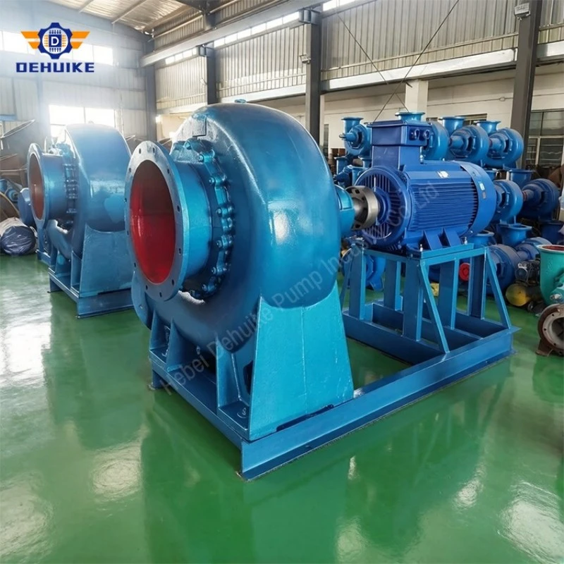
In a wet-pit station, the bowl sits in the water and a column carries the shaft to a motor on a floor above. There is no priming, no suction pipe, and very little civil work. Access is the price: the wheel stays out of sight until the column comes up, so monitoring falls to a level probe, a vibration sensor and a current recorder.
A dry-pit station puts the pump on a floor beside the basin, with a suction pipe through the wall and a foot-mounted motor at the same level. Inspection is easy and a standard motor can be used. The trade is a longer suction line, priming after any drain-down, and a floor area that has to be kept dry.
Whichever layout is chosen, the civil drawings need three things: a floor that is truly level, a back wall set well behind the bellmouth, and a low-level trip that a jammed float cannot override.
Technical FAQ: Axial Engineering, Siphon Operation, and Maintenance
Q1: What mechanical principles differentiate an Axial Mixed Flow Pump from a traditional radial volute unit?
Radial volute pumps force fluid outward at a 90-degree angle from the inlet axis, converting velocity to pressure inside an asymmetric spiral casing. This design produces high discharge head but restricts total flow. An Axial Mixed Flow Pump directs fluid diagonally through wide-span blades into an inline diffuser bowl, accelerating fluid predominantly along the axis. This hydraulic path achieves much higher volumetric delivery at moderate dynamic heads (20 m), accompanied by lower turning shear and improved efficiency at high specific speeds.
Q2: How does the DHW series perform in siphon discharge pipelines?
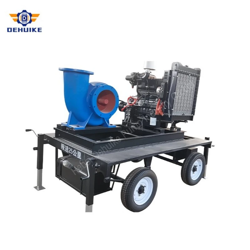
In low-lift river and canal crossings, siphon piping eliminates the need for expensive mechanical discharge valves. Because the DHW pump generates high initial flow at 1450 r/min, it rapidly evacuates air trapped in the crown of the siphon conduit, establishing full siphon flow automatically. Once siphon flow is primed, dynamic head drops to the elevation difference between water levels plus line friction, allowing the pump to operate at peak fuel economy.
Q3: Can the DHW diagonal runner handle silt-laden river intake water?
Yes. Because the diagonal blades are wide-spaced without narrow shrouding, the runner passes suspended clay, fine sand, and organic agricultural particles without clogging. Running at 1450 r/min keeps peripheral tip velocity low, which reduces abrasive wear by over 70% compared to 2900 r/min pumps. Optional wear-resistant alloy coatings and tungsten carbide shaft sleeves are available for extreme sediment loads.
Q4: What routine maintenance is required for continuous agricultural operation?
Routine maintenance is straightforward: check diesel oil and coolant levels prior to daily startup, inspect stuffing box drip rate (maintaining 20 to 60 drops per minute for packing lubrication and cooling), and lubricate bearing brackets with EP2 lithium grease every 500 operating hours. Replace diesel engine oil and filters after the first 50 break-in hours and every 250 operating hours thereafter.
Q5: What international crating and shipping options does Dehuike provide?
All pumps are completely drained, protected internally with anti-corrosion fluid, and sealed at flange openings. Assemblies are secured to solid timber skids and crated in fumigated ISPM-15 plywood boxes. Dehuike supports global ocean freight (LCL/FCL) and express air freight under Incoterms 2020 (FOB Chinese export ports and CIF global destination ports).

Hot Tags: axial mixed flow pump, China axial mixed flow pump manufacturers, suppliers, factory