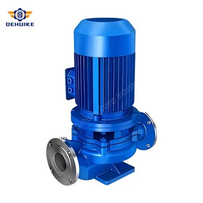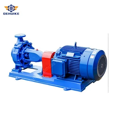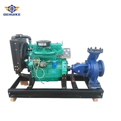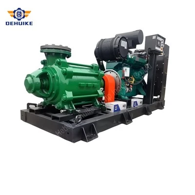
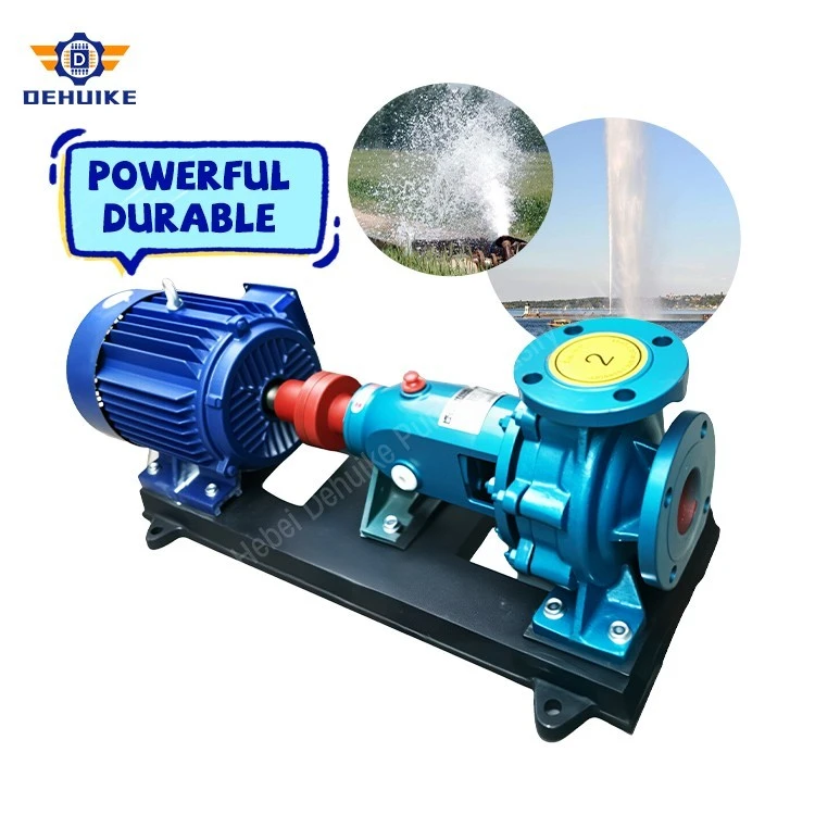
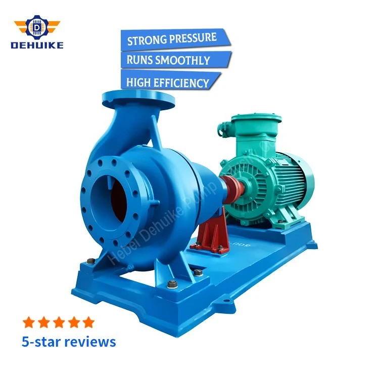
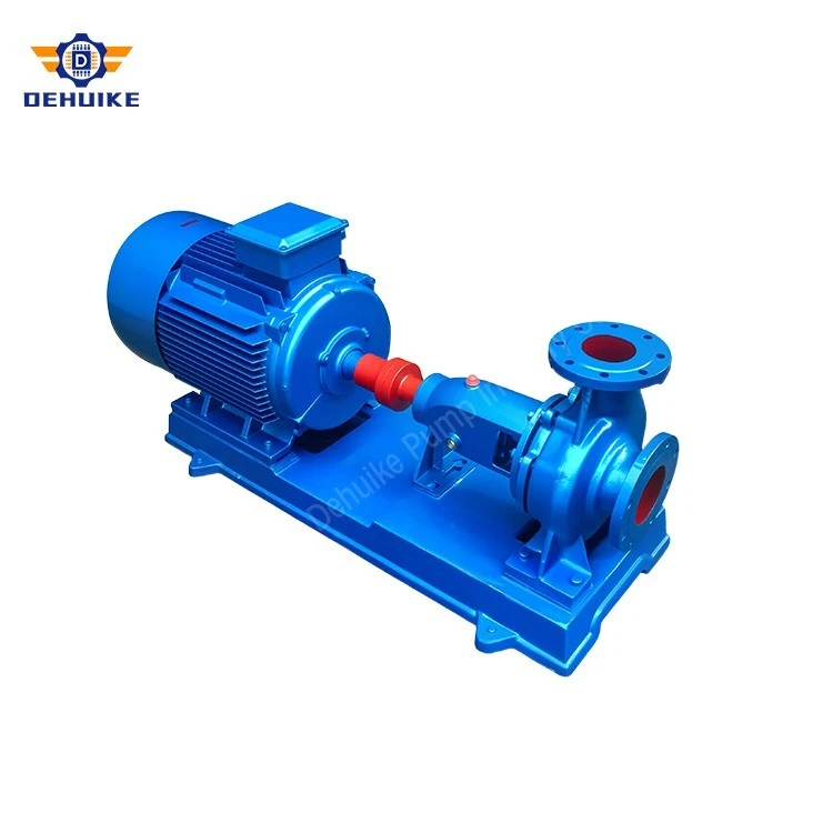
Hebei Dehuike Pump Industry Co., Ltd. is one of the most reliable manufacturers and suppliers of is end suction transfer pump in China. With abundant experience, we are committed to providing high quality customized pumps with competitive price. Welcome to wholesale bulk is end suction transfer pump for sale here from our factory. Also, pricelist is available.
Introduction - Industrial Liquid Logistics & Continuous Inter-Facility Transfer Standards
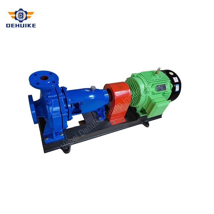
Liquid Logistics Foundation & Global Standard: The IS End Suction Transfer Pump provides the foundational mechanical pumping architecture for continuous bulk fluid handling across industrial manufacturing complexes, tank farm logistics terminals, municipal treatment plants, and facility water conveyance grids. Engineered strictly to the standardized ISO 2858 horizontal end-suction single-stage centrifugal design framework, this machine delivers dependable volumetric conveyance of utility water, process effluents, and chemical feedstocks between storage reservoirs, processing units, and elevated distribution systems.
Continuous S1 Duty Cycle & Variable Tank Level Dynamics: In continuous manufacturing operations-such as pulp and paper mills, chemical manufacturing complexes, thermal power stations, and municipal bulk water distribution stations-fluid transfer machinery must operate under continuous S1 duty cycles (24 hours per day, 365 days per year). Fluid levels in upstream supply tanks fluctuate continuously, varying from flooded positive suction heads when tanks are full down to low liquid levels nearing atmospheric suction lift. The IS End Suction Transfer Pump features an optimized volute intake and balanced radial-flow impeller designed with low Net Positive Suction Head requirements (NPSHr), ensuring smooth hydraulic intake without inducing destructive cavitation or vibration as liquid levels deplete.
Operational Temperature Envelope & Fluid Compatibility: Constructed from high-grade HT200 or HT250 pearlite grey cast iron (with optional cast steel or bronze configurations), the transfer pump casing exhibits exceptional structural rigidity and mechanical damping. It handles operating fluid temperatures spanning from -20°C up to +105°C (extendable to +140°C with high-temperature mechanical seals and external cooling jackets). Internal waterways are engineered to convey clean water, filtered process fluids, and non-abrasive aqueous solutions with particulate content strictly below 0.1% by volume and maximum particle diameters under 0.2 mm.
Procurement Lifecycle ROI & Universal Spare Parts Interchangeability: From a total cost of ownership (TCO) and procurement perspective, the IS End Suction Transfer Pump offers exceptional financial return across its operating lifespan. Its standardized dimensional interface allows plant operators to swap pumps across international piping manifolds without torching or modifying fixed civil foundation plinths. Furthermore, standardized internal rotating parts maximize interchangeability across multiple pump sizes within the same industrial park, substantially lowering spare parts inventory carrying costs.
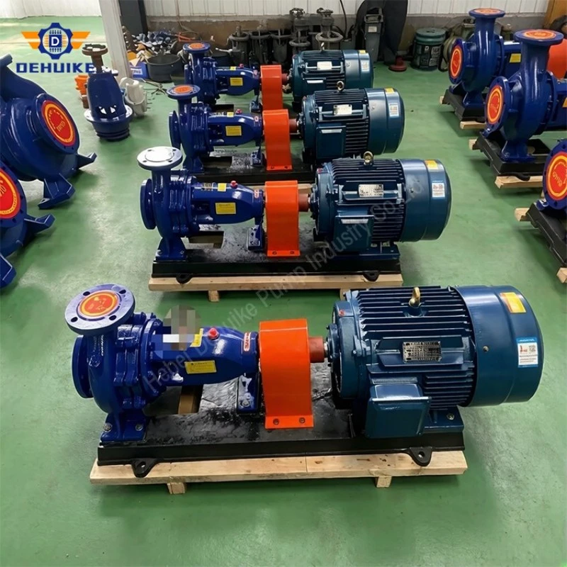
Product Details - Hydrodynamic Spiral Volute, ISO 1940 G2.5 Impeller Dynamics, and Engineered Chemical-Grade Sealing
Precision Heavy Industrial Subassembly: The physical construction of the IS End Suction Transfer Pump integrates precision foundry metallurgy with computerized multi-axis CNC machining, producing a robust mechanical unit optimized for continuous industrial fluid conveyance.
Hydraulic Volute Geometry & High-Stiffness Mounting Feet: The single-volute casing features an axial end-suction inlet nozzle and a vertical centerline discharge branch conforming to ISO 7005-2 / DIN 2501 PN16 flanged connections. The internal spiral volute geometry is engineered with progressive cross-sectional area expansion, smoothly converting high-velocity kinetic energy into static pressure with minimal fluid shear and wall friction. Heavy-duty cast iron mounting feet are cast integrally onto the volute base, directly bolting to structural baseplates to absorb piping nozzle loads without transferring deflection to the rotating shaft.
Dynamically Balanced Impeller & Axial Thrust Equalization: The enclosed radial-flow impeller is cast from dense HT200 cast iron or optional silicon bronze, featuring aerodynamically profiled backward-curved vanes. Every impeller is dynamically balanced on digital two-plane balancing machines to ISO 1940 Grade G2.5, ensuring residual unbalance is kept below 0.5 g·mm/kg. Front and rear shrouds are precision-machined to mate with replaceable casing wear rings (radial clearance maintained between 0.25 and 0.40 mm), while back-shroud relief holes continuously vent pressure back to the suction eye, neutralizing up to 85% of net axial hydraulic thrust.
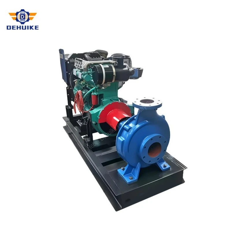
High-Tensile 40Cr Alloy Shaft & Replaceable Stainless Sleeve: The horizontal drive shaft is precision-machined from forged 40Cr alloy steel, quenched and tempered to 240-280 HBW to resist cyclic bending fatigue and torsional shear stresses. In the sealing chamber, the shaft is fully encased in a renewable 2Cr13 stainless steel shaft sleeve, ground to a mirror finish. This design ensures that corrosive fluids and abrasive particles never make contact with the structural shafting, allowing inexpensive sleeve replacement during routine plant overhauls.
Engineered Mechanical Sealing Chamber & API Plan 11 Flush: The stuffing box backplate is designed to accommodate multiple sealing arrangements tailored to the transferred fluid. For leak-free chemical and utility transfer, balanced cartridge mechanical seals featuring solid Silicon Carbide versus Tungsten Carbide running faces with Viton or PTFE secondary elastomers are installed, coupled with an API Plan 11 bypass flush line to circulate cooling fluid across the seal faces. For non-critical raw water transfer, soft braided PTFE-graphite gland packing with an internal bronze lantern ring provides reliable, field-adjustable sealing.
Features/Equipment Characteristics - Broad Operating Envelope, Low NPSHr Suction Margins, and True Back-Pull-Out Plant Maintenance
Key Operational Performance Hallmarks: The functional design of the IS End Suction Transfer Pump provides distinctive operational capabilities that enhance plant uptime and reduce maintenance labor overhead.
Broad Volumetric Transfer Scalability Across Plant Utilities: The pump provides broad volumetric transfer capability, scaling from compact 15 m³/h utility flows up to large 120 m³/h bulk conveyance streams, with developed discharge pressure heads ranging from 6.0 meters up to 57.5 meters (0.575 MPa). This broad coverage allows engineering procurement teams to standardize on a single equipment series across diverse plant fluid duties.
Straight-In Suction Hydrodynamics & Low NPSHr Margin: Incoming fluid travels along a straight, horizontal suction nozzle directly into the center of the impeller eye without tortuous 90-degree internal turns. This straight-in hydrodynamics delivers remarkably low Required Net Positive Suction Head (NPSHr), ranging from 2.0 to 4.5 meters across standard operating frames. This generous suction margin enables the pump to decant deep industrial sumps or drain chemical storage tanks down to their bottom heel without inducing cavitation.
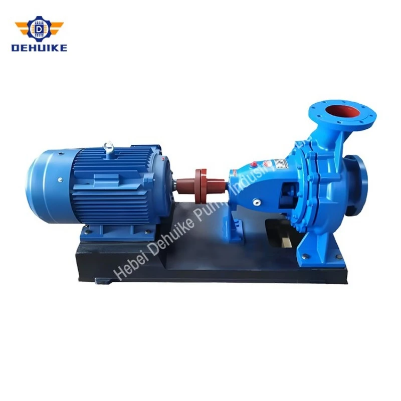
True Back-Pull-Out Rapid Overhaul Architecture: The back-pull-out structural execution is a signature maintenance advantage. Maintenance personnel can withdraw the entire rotating element-comprising the bearing bracket, drive shaft, mechanical seal backplate, and impeller-toward the motor end without disturbing the suction or discharge piping. When installed with an extended spacer-type flexible coupling, the electric drive motor remains firmly bolted to the baseplate, reducing mechanical seal or bearing inspection times to under 45 minutes.
Vibration Dampening & Structural Foundation Rigidity: The rigid cast iron bearing housing, heavy foundation anchoring, and precision shaft alignment deliver exceptional vibrational stability. Operational vibration velocities remain well below 1.8 mm/s RMS (conforming to ISO 10816-3 Grade A), protecting adjacent pipe joints, pressure transmitters, and building structures from acoustic resonance and mechanical fatigue.
Specifications/Technical Parameters - High-Throughput Transfer Matrix Across Full-Diameter, Trim-A, and Trim-B Configurations
Liquid Transfer Performance Calibration: To assist chemical process designers, piping network consultants, and industrial utility engineers in matching pump hydrodynamics to plant friction head profiles, the operational data of the IS End Suction Transfer Pump are cataloged below across three segregated impeller diameter series: Standard Full-Diameter Models (Series 1), Primary Trimmed Models (Series 2 Trim-A), and Secondary Trimmed Models (Series 3 Trim-B). All listed figures reflect verified hydrostatic and hydraulic test measurements recorded on automated test benches.
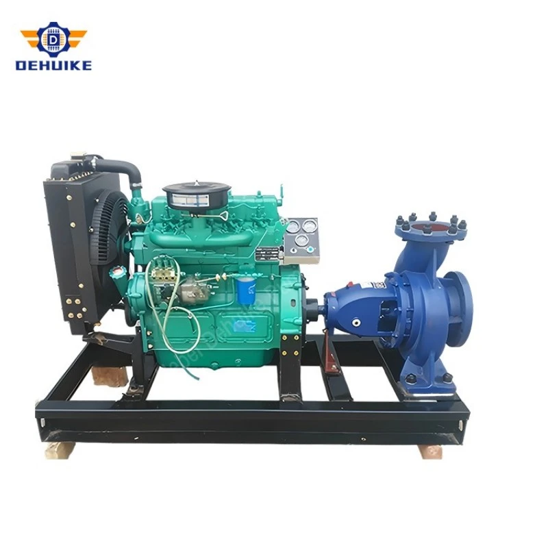
4.1 Standard Full-Diameter Transfer Models (Series 1: Maximum Diametral Capacity)
Series 1 Duty Profile: Series 1 covers untrimmed full-diameter impellers designed for maximum volumetric transfer and high dynamic head generation. Operating at 2900 RPM speeds, models like the IS 80-65-160, IS 100-65-200, and IS 125-100-200 provide concentrated dynamic heads up to 57.5 meters for moving fluids through long inter-facility pipeline corridors. Operating at 1450 RPM speeds, units like the IS 100-80-125 and IS 150-125-250 deliver high-efficiency bulk transfer up to 120 m³/h with minimum power consumption.
|
Model Designation |
Speed (r/min) |
Rated Flow (m³/h) |
Rated Head (m) |
Peak Eff. (%) |
NPSHr (m) |
Mating Motor |
Inlet / Outlet (mm) |
|
IS 80-65-160 |
2900 |
50.0 |
32.0 |
61.0 |
2.5 |
7.5 kW (Y132S2-2) |
80 / 65 |
|
IS 80-65-160 |
1450 |
25.0 |
8.0 |
55.0 |
2.5 |
1.5 kW (Y90L-4) |
80 / 65 |
|
IS 100-80-125 |
1450 |
30.0 |
6.0 |
64.0 |
4.0 |
1.5 kW (Y90L-4) |
100 / 80 |
|
IS 100-65-200 |
2900 |
60.0 |
54.0 |
65.0 |
3.0 |
22.0 kW (Y180M-2) |
100 / 65 |
|
IS 125-100-200 |
2900 |
120.0 |
57.5 |
67.0 |
4.5 |
45.0 kW (Y225M-2) |
125 / 100 |
|
IS 150-125-250 |
1450 |
120.0 |
22.5 |
71.0 |
3.0 |
18.5 kW (Y180L-4) |
150 / 125 |
Data Interpretation: Listed values under Flow and Head correspond to the Rated Optimal Efficiency Point (BEP). Bare pump weights vary between 44 kg on the compact IS 80-65-160 and 164 kg on the IS 150-125-250 casting. Flange dimensions comply with ISO 7005-2 PN16 drillings.
4.2 Primary Trimmed Transfer Models (Series 2: First-Stage Impeller Trimming)
Series 2 Impeller Trimming A Engineering Logic: Series 2 incorporates factory-machined first-stage trimmed impellers ('A' suffix). In facility transfer loops where piping friction losses are moderate, operating an untrimmed impeller forces plant operators to throttle discharge valves, introducing unwanted hydraulic noise and wasting electrical power. Precision outer-diameter trimming aligns pump head output directly with plant system curves, lowering absorbed horsepower and allowing downsizing of electric drive motors.
|
Model Designation |
Speed (r/min) |
Rated Flow (m³/h) |
Rated Head (m) |
Peak Eff. (%) |
NPSHr (m) |
Mating Motor |
Inlet / Outlet (mm) |
|
IS 80-65-160A |
2900 |
27.0 |
30.5 |
60.0 |
2.5 |
5.5 kW (Y132S1-2) |
80 / 65 |
|
IS 80-65-160A |
1450 |
14.0 |
7.9 |
54.0 |
2.5 |
1.1 kW (Y90S-4) |
80 / 65 |
|
IS 100-80-125A |
1450 |
26.9 |
4.8 |
57.0 |
2.5 |
1.1 kW (Y90S-4) |
100 / 80 |
|
IS 100-65-200A |
2900 |
56.1 |
47.6 |
65.0 |
3.0 |
18.5 kW (Y160L-2) |
100 / 65 |
|
IS 125-100-200A |
2900 |
112.5 |
50.5 |
65.0 |
4.5 |
37.0 kW (Y200L2-2) |
125 / 100 |
|
IS 150-125-250A |
1450 |
112.0 |
19.7 |
68.5 |
3.0 |
15.0 kW (Y160L-4) |
150 / 125 |
Hydraulic Analysis: First-stage impeller trimming maintains optimal hydraulic efficiency within 0.5% to 2.0% of nominal baseline ratings. On model IS 125-100-200A at 2900 RPM, motor power rating steps down from 45.0 kW to 37.0 kW while sustaining a high 112.5 m³/h transfer flow at 50.5 meters head, delivering major annual electricity savings in continuous plant utility service.
4.3 Secondary Trimmed Transfer Models (Series 3: Second-Stage Impeller Trimming)
Series 3 Impeller Trimming B Power & Cavitation Protection: Series 3 features secondary trimmed impellers ('B' suffix) designed for low-differential pressure fluid transfer between adjacent holding tanks or secondary decanting sumps. In low-head pipelines, secondary trimming prevents electric motors from operating under partial load where power factor declines, ensuring that the motor operates near its optimal 90% load point while preventing fluid recirculation cavitation at the impeller tips.
|
Model Designation |
Speed (r/min) |
Rated Flow (m³/h) |
Rated Head (m) |
Peak Eff. (%) |
NPSHr (m) |
Mating Motor |
Inlet / Outlet (mm) |
|
IS 80-65-160B |
2900 |
24.0 |
25.0 |
59.0 |
2.5 |
4.0 kW (Y112M-2) |
80 / 65 |
|
IS 80-65-160B |
1450 |
13.0 |
6.8 |
53.0 |
2.5 |
0.75 kW (Y802-4) |
80 / 65 |
|
IS 100-65-200B |
2900 |
52.0 |
41.0 |
65.0 |
3.0 |
15.0 kW (Y160M2-2) |
100 / 65 |
|
IS 125-100-200B |
2900 |
95.0 |
42.0 |
62.5 |
4.5 |
22.0 kW (Y180M-2) |
125 / 100 |
|
IS 150-125-250B |
1450 |
104.0 |
16.9 |
64.5 |
2.5 |
11.0 kW (Y160M-4) |
150 / 125 |
Energy Optimization: Comparing the full-diameter IS 125-100-200 at 2900 RPM (45.0 kW motor) with its Type B counterpart IS 125-100-200B (22.0 kW motor), installed electrical capacity drops by 23.0 kW (a 51.1% power reduction). This makes Series 3 ideal for industrial facilities optimizing factory electrical load allocations while avoiding costly throttling valve wear.
Our Advantages - Superior Hydraulic Stability, S1 Continuous Duty Reliability, and Fast On-Site Plant Overhaul
Comparative Liquid Logistics Superiority: In comparative engineering evaluations against positive displacement gear pumps, vertical inline pumps, and split-case units for bulk liquid logistics, the IS End Suction Transfer Pump delivers pronounced operational and financial advantages.
Continuous Laminar Flow Versus Positive Displacement Pulsation: Unlike positive displacement gear or screw pumps that produce pulsating fluid flow and require pressure relief valves to prevent piping over-pressurization, the centrifugal IS pump delivers smooth, continuous laminar discharge. Its centrifugal pressure-limiting characteristic prevents catastrophic pipe rupture if downstream valves are inadvertently shut, ensuring safe continuous operation in chemical and utility transfer manifolds.
Physical Separation of Motor and Fluid Chamber: Compared to vertical inline pumps whose electric motors sit directly above the pump casing and are exposed to rising chemical vapors and moisture, the IS horizontal pump separates the drive motor and bearing housing by an expansive open air gap. This layout prevents liquid leakage from reaching the motor windings, guaranteeing long motor insulation life in continuous S1 industrial service.
Simplified On-Site Maintenance & Low Overhaul Overhead: From a plant maintenance budgeting standpoint, the IS pump delivers lowest total lifecycle cost. The true back-pull-out structural execution allows on-site plant mechanics to perform complete mechanical seal replacements and bearing repacking directly on the foundation plinth, avoiding the heavy crane rigging and pipe disconnection required by double-suction split-case pumps.
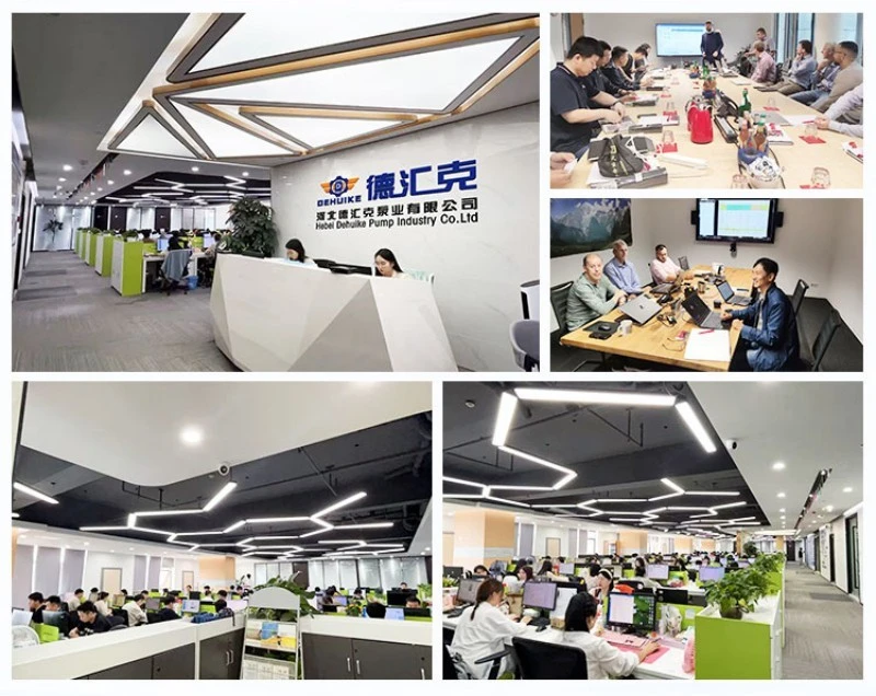
Production Process - Automated Shell Molding, Stress-Relief Heat Treatment, and Computerized CMM Inspection
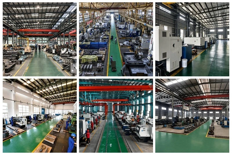
Multi-Tier Industrial Quality Assurance: The manufacturing protocols for the IS End Suction Transfer Pump enforce rigorous quality gates across metallurgical casting, stress-relief heat treatment, and precision multi-axis CNC machining at Hebei Dehuike Pump Industry Co., Ltd.
Automated Shell Molding & Metallurgical Verification: Pump casings and bearing brackets are cast using automated phenolic-resin shell molding machines. Molten grey iron is processed in electric induction furnaces, with continuous spectrographic melt monitoring ensuring a high pearlite fraction (>90%) with uniform Type-A graphite flake distribution. This microstructural consistency produces high damping capacity and prevents micro-shrinkage porosity across pressurized volute walls.
Thermal Stress Relieving & Single-Clamping CNC Machining: Raw castings are subjected to computer-controlled thermal stress-relieving cycles (soaking at 550°C to 600°C followed by controlled furnace cooling) to dissipate residual casting stresses. CNC horizontal boring and turning centers then machine all critical register spigots, wear ring bores, and shaft seal cavities in a single setup, guaranteeing concentricity within 0.015 mm.
CMM Metrology & ISO 9906 Certified Hydraulic Verification: Following machining, components are inspected on three-coordinate measuring machines (CMM) to verify dimensional compliance. Assembled bare-shaft pumps undergo hydrostatic testing at 1.5 times maximum working pressure (up to 2.4 MPa) for 30 minutes with zero allowable pressure drop, followed by full-spectrum performance verification on digital hydraulic test loops compliant with ISO 9906 Grade 2B.
Application - Bulk Chemical Tank Farms, Power Plant Cooling Basins, Industrial Water Utilities, and Municipal Water Transfer
Primary Liquid Logistics Application Sectors: The broad hydraulic envelope, continuous S1 reliability, and standardized construction of the IS End Suction Transfer Pump enable widespread deployment across demanding liquid logistics sectors.
Chemical Tank Farm Decanting & Terminal Logistics Manifolds: In bulk chemical storage terminals, oil refineries, and tank farms, IS pumps decant incoming railcars and tank trucks into primary bulk holding tanks, and circulate liquid products through terminal piping headers to packaging lines and distribution manifolds.
Power Generation Cooling Tower Basin Circulation & Make-Up: In thermal power generation stations and district energy facilities, heavy-duty IS units circulate cooling tower basin water through plate heat exchangers and surface condensers, providing constant high-volume water replenishment to maintain plant thermal efficiency.
Industrial Park Raw Water Conveyance & Inter-Building Mains: Across automotive assembly complexes, steel manufacturing facilities, and industrial parks, IS pumps transfer raw utility water from central river or reservoir intake stations through miles of buried distribution mains, feeding boiler houses, cooling circuits, and fire buffer tanks.
Municipal Water Treatment Clarifier Decanting & Filter Backwash: In municipal clean water treatment facilities, IS pumps transfer clarified water from sedimentation basins through dual-media sand filters and into regional finished-water distribution clearwells, supporting municipal grid water pressures round the clock.
Our Service, Experience and Markets & - Dehuike Four-Decade Engineering Foundation, Turnkey Transfer Skids, and Worldwide Export Track Record
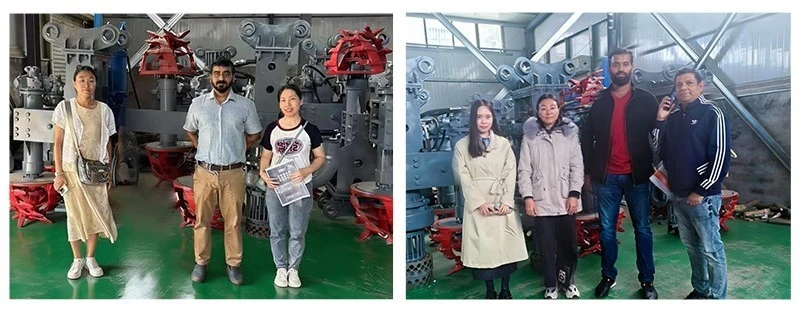
Four Decades of Liquid Machinery Engineering Heritage: Hebei Dehuike Pump Industry Co., Ltd. (DHK Pump) combines more than forty years of specialized rotodynamic fluid machinery manufacturing with global turnkey skid engineering, delivering certified liquid transfer solutions to industrial process facilities worldwide.
Engineered Transfer Skids & Pre-Aligned Packaging: Dehuike's manufacturing portfolio spans over 30 distinct product lines of centrifugal, slurry, and multi-stage pumps. For industrial liquid logistics and bulk transfer upgrades, our application engineering team designs integrated skid packages-mounting the bare pump, fabricated structural steel channel base, high-efficiency motor (IE3/IE4), flexible spacer coupling, and OSHA-compliant coupling guard into a pre-aligned, drop-in assembly.
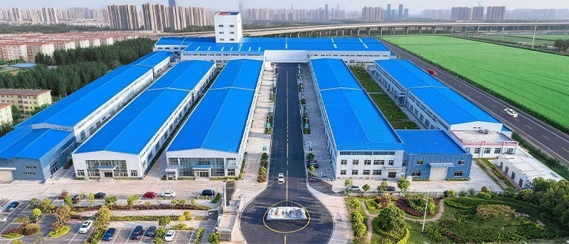
8,000+ m² Production Infrastructure & Rapid Dispatch: Manufacturing operations are centered in a specialized 8,000+ square meter industrial facility equipped with advanced casting foundries, multi-axis CNC machining bays, and certified hydraulic test facilities. Backed by a verified network of over 900 regional component suppliers, Dehuike maintains substantial stocks of standard volute casings, 40Cr shafts, and dynamically balanced impellers, enabling rapid dispatch of standard pump skids within 10 to 15 working days.
Proven Global Deployment Across 90+ Countries: Dehuike fluid transfer equipment operates in continuous industrial duty across more than 90 countries and territories worldwide. Our installations support chemical transfer terminals in Germany, refinery utility loops in the United Arab Emirates, copper mine water conveyance in Chile, and municipal water treatment plants in Malaysia, delivering proven hydraulic reliability across extreme ambient environments.
24-Month Comprehensive Warranty & Industrial Engineering Support: Every IS End Suction Transfer Pump is backed by Dehuike's comprehensive 2-year (24-month) factory warranty covering the complete machine (excluding standard consumable wear components like packing rings and mechanical seals). Our engineering department delivers full pre-order technical support, supplying 2D/3D BIM drawings, calculating pipe friction losses, and matching electric motors to international power grid specifications (220V, 380V, 400V, 415V, 440V, 460V, 480V, 660V at 50Hz or 60Hz, with IE2/IE3/IE4 efficiency standards and IP55/IP65/Ex-proof ratings).
Heavy Seaworthy Packaging & Global Multimodal Shipping: Export packaging enforces strict seaworthy protective discipline. Finished pump assemblies are treated with rust-preventative barriers, sealed inside heavy vapor corrosion inhibitor (VCI) protective bags, and bolted inside heat-treated, fumigated solid timber export crates reinforced with steel corner framing. International shipments are routed via ocean freight for container consignments exceeding 500 kg, and air freight for urgent spare parts (50 to 500 kg), contracted under standard FOB or CIF destination port incoterms.
Engineering FAQ: Specialized Technical Guidance for Industrial End Suction Transfer Pumps
Q1: What engineering measures prevent transient pressure surges (water hammer) in long overland transfer pipelines?
Stopping a centrifugal transfer pump suddenly on a long discharge main can generate severe negative pressure waves followed by destructive positive pressure surges (water hammer) capable of rupturing pipeline joints. Essential engineering safeguards include: (1) Installing a slow-closing, counter-weighted non-return check valve immediately downstream of the pump discharge; (2) Mounting a hydropneumatic surge suppression tank or bladder accumulator near the pump outlet; and (3) Utilizing a variable frequency drive (VFD) or digital soft-starter with programmable ramp-down deceleration profiles to gradually slow the fluid column.
Q2: How should engineering teams choose between operating the IS transfer pump at 2900 RPM versus 1450 RPM?
The choice depends on discharge head requirements and continuous run hours. If the application demands high pressure-such as overcoming long overland pipeline friction, feeding elevated storage tanks, or boosting water through fine filtration systems-2900 RPM provides the necessary dynamic head (up to 57.5 meters) in a compact footprint. For continuous 24/7/365 bulk fluid transfer at moderate heads, operating at 1450 RPM provides lower internal fluid velocities, significantly less wear on mechanical seals and bearings, lower noise levels (<68 dBA), and extended maintenance intervals exceeding 25,000 hours.
Q3: Which mechanical seal arrangement is recommended for continuous S1 duty liquid transfer with API Plan 11 flush?
For continuous S1 industrial service, Dehuike recommends a balanced cartridge mechanical seal featuring solid Silicon Carbide versus Tungsten Carbide running faces with Viton or EPDM secondary O-rings. An API Plan 11 flush-which routes a high-pressure bypass stream from the pump discharge through an orifice into the seal chamber-is essential. This flush maintains continuous fluid circulation across the seal faces, dissipating frictional heat and preventing vapor lock or dry-running during prolonged pumping cycles.
Q4: How should suction piping be configured to prevent cavitation when draining storage tanks down to low liquid levels?
When emptying bulk storage tanks, static suction head decreases as the liquid level drops. To maintain Net Positive Suction Head Available (NPSHa) above the pump's Required NPSH (NPSHr), the suction piping should: (1) Be sized one standard pipe diameter larger than the pump suction nozzle, connected via an eccentric reducer with the flat side on top to eliminate air pockets; (2) Incorporate a straight pipe run of at least 5 to 10 pipe diameters directly before the pump inlet; and (3) Use low-loss full-port ball or gate valves rather than high-resistance globe valves.
Q5: Can multiple IS transfer pumps operate in parallel on a common discharge manifold without hydraulic instability?
Yes, provided the pumps have continuously rising head curves from rated duty toward shutoff. When operating in parallel, the total flow rate equals the sum of the individual pump flows at the common discharge head. To ensure stable operation: (1) Identical pump models with matching impeller trims should be selected; (2) Dedicated check valves and isolation valves must be installed on each pump discharge branch; and (3) Suction manifolds must be symmetrically designed to ensure equal flow distribution into each pump suction eye.
Q6: How can electric motors be protected against overload during high-flow 'run-out' conditions when filling empty pipelines?
When starting up into a completely empty, unpressurized discharge pipeline, the pump experiences near-zero backpressure. In this state, centrifugal pumps operate far to the right of their design curve ('run-out' mode), delivering maximum flow and drawing peak shaft horsepower, which can trip thermal overloads or burn out undersized motors. To prevent this, the discharge isolation valve should be throttled to approximately 20%-30% open during initial pipeline filling, or the electric motor should be sized to cover the maximum end-of-curve power demand.

Hot Tags: is end suction transfer pump, China is end suction transfer pump manufacturers, suppliers, factory