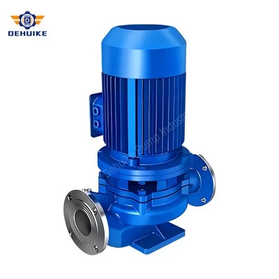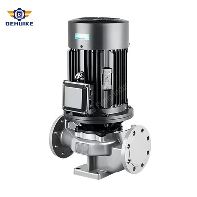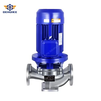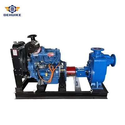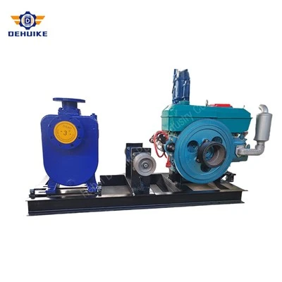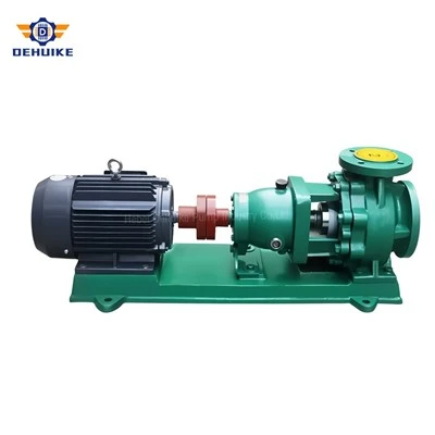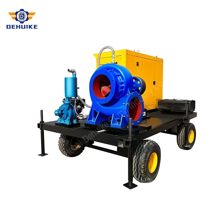
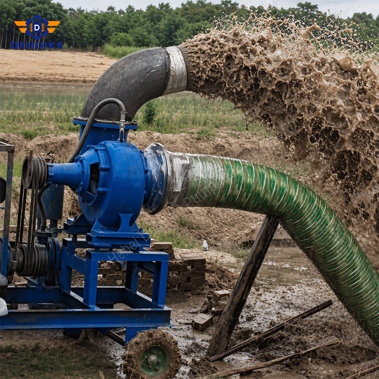
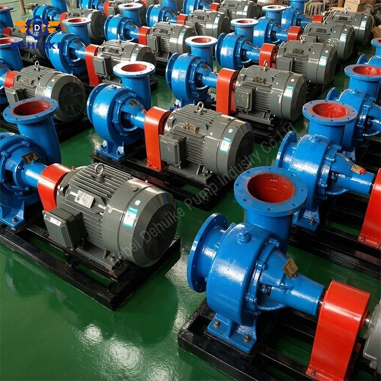
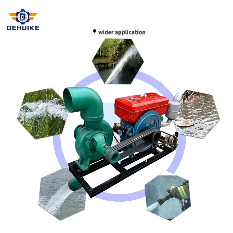
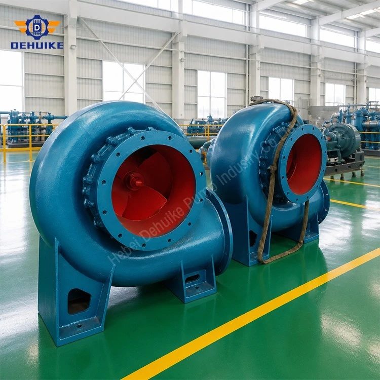
Hebei Dehuike Pump Industry Co., Ltd. is one of the most reliable manufacturers and suppliers of mixed flow water pump in China. With abundant experience, we are committed to providing high quality customized pumps with competitive price. Welcome to wholesale bulk mixed flow water pump for sale here from our factory. Also, pricelist is available.
Product Architecture | Move Water According to the Route and Receiving Demand
A Mixed Flow Water Pump is considered when a water-transfer project needs a hydraulic arrangement combining axial and radial flow components. The useful starting point is the route: the source level, the destination, the volume needed and the losses between them. Irrigation, reservoir transfer and suitable drainage duties can present very different conditions. Selecting a pump for those conditions is more informative than choosing a machine solely because its discharge diameter appears large enough.
Inside the hydraulic element, the impeller gives the water energy while directing it through a mixed-flow passage. The discharge direction has both axial and radial components relative to the rotating assembly. This identifies the hydraulic principle, but it does not establish a universal head range or an efficiency advantage over every other pump type. The selected curve, construction and installation determine whether a particular model is appropriate for the task being considered.
For a real transfer route, the pump and network must be considered together. The delivered flow follows the relationship between the pump characteristic and the resistance presented by the installation. A longer discharge route, lower source level or changed receiving condition can move the operating point. The curve should therefore be reviewed for expected variations, including seasonal conditions, rather than treating a nominal model reference as constant output under all circumstances.
The DHW references in this article identify four proposed models with different discharge sizes. The original schedule associates each with 1450 r/min and 20 m head, but its engine entries do not reconcile with the listed hydraulic duties. Those entries are retained for traceability and flagged for correction. A Mixed Flow Water Pump proposal should use a manufacturer-confirmed combination of capacity, head, absorbed power and driver before any performance or fuel-cost commitment is made.
Technical Specifications | Separate Hydraulic References from Driver Approval
The selection schedule is organized in the same compact, intermediate and larger-capacity groups as the product range. This helps compare connection geometry and intended scale without combining unrelated figures. Every duty must still be represented by a complete, verified record. A maximum flow, common head and small engine cannot be assembled into a new rating simply because they appear in the same catalogue. Driver approval is a separate engineering check alongside hydraulic selection.
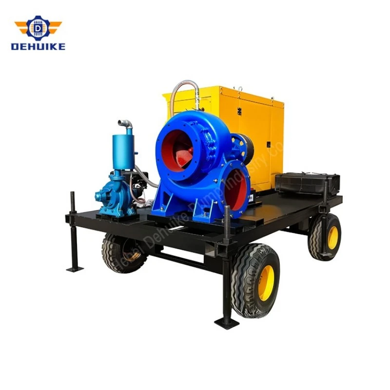
2.1 Compact Reference | DHW250-20 and the Initial Layout Review
DHW250-20 is listed with a 100 mm discharge connection and a reference condition of 250 m³/h at 20 m. These numbers should be reviewed together on the actual performance curve before a project is designed around them. A smaller connection can affect routing and installation choices, but it does not by itself demonstrate portability or acceptable pipeline loss. Obtain the pump dimensions, complete assembly mass and connection details relevant to the proposed package.
|
Model Designation |
Discharge Outlet |
Rated Capacity (Q) |
Rated Head (H) |
Rotational Speed |
Source engine entry - UNVERIFIED |
Drive Adaptability |
|
DHW250-20 |
100 mm |
250 m³/h |
20 m |
1450 r/min |
8 HP |
Diesel engine / Electric motor / Tractor PTO |
The associated 8 HP entry cannot substantiate that hydraulic condition. For clean water, the theoretical power transferred to the liquid is already approximately 13.6 kW, before pump and drive losses, whereas 8 mechanical horsepower is about 6.0 kW. The capacity, head or driver data therefore needs correction. Do not use the entry to claim continuous performance, reserve torque, low fuel consumption or a particular mobile-package weight until a consistent equipment record is available.
2.2 Intermediate References | DHW280-20 and DHW300-20
The intermediate group lists 125 mm and 150 mm discharge connections. These differences matter to the installation drawing and mating pipework, while the route calculation establishes the required pipe size and losses. A larger pump outlet does not independently determine how much water reaches the receiving point. Review the full suction and discharge arrangements, including any temporary hoses or permanent fittings, when comparing the two proposed references for a field installation.
DHW280-20 is recorded at 280 m³/h and DHW300-20 at 300 m³/h, each with 20 m head and 1450 r/min. The listed engines are 8 HP and 15 HP respectively. At those water duties, theoretical hydraulic powers are approximately 15.3 kW and 16.4 kW, exceeding the corresponding engine ratings before losses. The source figures must be reconciled; they cannot support claims that one model delivers extra volume with unchanged fuel demand or that the other has a demonstrated pressure reserve.
|
Model Designation |
Discharge Outlet |
Rated Capacity (Q) |
Rated Head (H) |
Rotational Speed |
Source engine entry - UNVERIFIED |
Drive Adaptability |
|
DHW280-20 |
125 mm |
280 m³/h |
20 m |
1450 r/min |
8 HP |
Diesel engine / Electric motor / Tractor PTO |
|
DHW300-20 |
150 mm |
300 m³/h |
20 m |
1450 r/min |
15 HP |
Diesel engine / Electric motor / Tractor PTO |
For agricultural enquiries, compare these models using corrected performance information and the actual water task. State the period available for pumping and the required volume, then determine the relevant delivery rate. Add source levels and route details so the hydraulic selection reflects field conditions. A farm's area alone cannot identify the correct pump, and a preferred engine size cannot establish the capacity needed at the destination. The proposed package must resolve both requirements together.
2.3 Larger Reference | DHW580-20 and Complete Package Planning
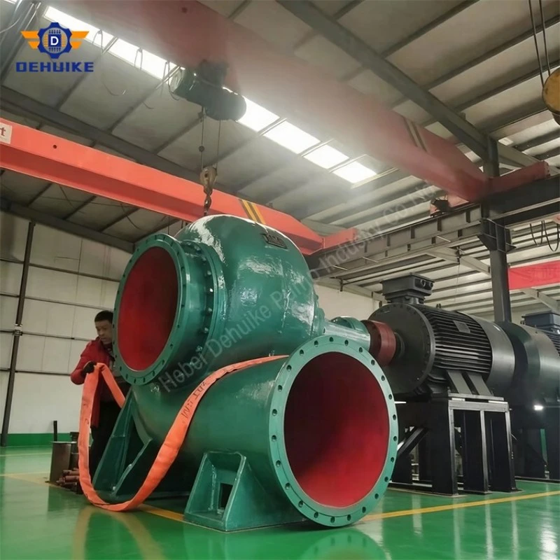
DHW580-20 has a listed 200 mm discharge and a proposed capacity of 580 m³/h at 20 m. It is a candidate reference for a higher-volume discussion, subject to corrected curve and driver information. At this scale, the installation review should include access, pipe support, handling and the receiving route. A large nominal capacity does not demonstrate readiness for flood response or prove that an unspecified trailer, priming system or auxiliary device is included.
|
Model Designation |
Discharge Outlet |
Rated Capacity (Q) |
Rated Head (H) |
Rotational Speed |
Source engine entry - UNVERIFIED |
Drive Adaptability |
|
DHW580-20 |
200 mm |
580 m³/h |
20 m |
1450 r/min |
22 HP |
Diesel engine / Electric motor / Tractor PTO |
The schedule associates this condition with 22 HP, approximately 16.4 kW of engine rating. The theoretical hydraulic output for clean water is about 31.6 kW, so that pairing is inconsistent even before efficiency and transmission are considered. The conversion of 580 m³/h to roughly 161 L/s is arithmetically valid, but it is not evidence that the listed engine can produce the duty. A corrected manufacturer record is required before predicting actual drainage time or continuous output.
2.4 Consolidated Schedule | Original Values Requiring Reconciliation
The tables preserve the original model, connection, speed and rating entries so the information can be traced back to the product record. Their driver columns are expressly unverified for the stated hydraulic conditions. For clean water, hydraulic output follows density × gravity × volume flow × head using consistent units. The calculated outputs above are minimum theoretical water powers, not recommended driver sizes. Final sizing also requires the pump's absorbed power and applicable drive and operating conditions.
|
Tier / Classification |
Model |
Discharge Port |
Nominal Flow |
Rated Head |
Speed |
Source engine entry - UNVERIFIED |
Drive Options |
|
Tier 1: Compact Mobility |
DHW250-20 |
100 mm |
250 m³/h |
20 m |
1450 r/min |
8 HP Diesel |
Diesel / Electric / Tractor |
|
Tier 2: Mid-Range Diversion |
DHW280-20 |
125 mm |
280 m³/h |
20 m |
1450 r/min |
8 HP Diesel |
Diesel / Electric / Tractor |
|
Tier 2: High-Volume Irrigation |
DHW300-20 |
150 mm |
300 m³/h |
20 m |
1450 r/min |
15 HP Diesel |
Diesel / Electric / Tractor |
|
Tier 3: Heavy Municipal Flood |
DHW580-20 |
200 mm |
580 m³/h |
20 m |
1450 r/min |
22 HP Diesel |
Diesel / Electric / Tractor |
3. Product Construction | Follow the Water Passage and Mechanical Drive
The assembly should be described through its actual parts and interfaces. A casing, impeller, shaft, bearings and seal each performs a different function and needs an identified construction. A general statement about heavy-duty service cannot establish the details of all five. For the Mixed Flow Water Pump being offered, obtain the applicable arrangement and parts drawings, then connect the material and auxiliary selections with the water condition and intended operating environment.
3.1 Casing | Pressure Boundary Connections and Drainage Access
The casing carries water from the inlet region towards the discharge and provides the principal connection interfaces. The offered material, allowable pressure conditions and mounting geometry should be stated for the selected model. Cast iron or another proposed construction needs assessment against the liquid and project requirements. Nominal discharge diameter is insufficient for fabrication: flange drilling, face arrangement and pressure designation must match the actual assembly. Include access for any provided drain and follow the preservation instructions for seasonal storage.
3.2 Impeller | Identify the Hydraulic Configuration Being Supplied
Impeller geometry establishes the hydraulic configuration and must correspond to the selected curve. Material alternatives should be identified for the particular water rather than presented as universal upgrades. Where the liquid carries contamination, submit its nature and extent for assessment. A broad passage description does not establish a guaranteed solids limit or clog-free service. The replacement reference should retain the correct geometry and material identity so later maintenance does not unknowingly alter the selected performance.
3.3 Shaft and Bearings | Support the Rotating Assembly as Specified
The shaft transmits drive to the impeller, while the bearing arrangement locates and supports the rotating assembly. Sleeves, where included, form replaceable interfaces around the sealing region. Request the actual grades and component references rather than assuming every listed material is fitted. Lubrication and protection provisions should follow the supplied construction. Their service requirements belong in the operating instructions, with access maintained for observation and maintenance after the complete package has been installed.
3.4 Shaft Seal | Match the Arrangement to the Liquid and Operating Routine
Packing and mechanical seals require different operating attention. Identify the type offered, the replaceable components and any auxiliary service needed. A packing arrangement should be operated according to its applicable instructions; a generic leakage target or adjustment increment is not a universal procedure. Mechanical-seal selection likewise depends on the supplied chamber and liquid conditions. The owner should know what is fitted and which checks apply, without relying on a general promise that one construction guarantees zero leakage.
3.5 Drive Arrangements | Select the Transmission with the Pump
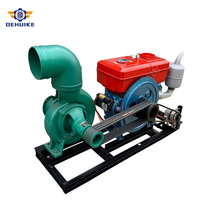
A Mixed Flow Water Pump may be considered with an electric driver, an engine or a tractor-driven transmission where the manufacturer offers a suitable arrangement. These are separate package configurations rather than interchangeable accessories. Each needs a verified power requirement and compatible speed, direction and mechanical interface. The proposal should identify the complete drive path and the equipment supplied, particularly where the driver is provided by the customer instead of included in the pump order.
For an engine package, relate the pump's absorbed-power curve to the engine's applicable output and operating conditions. Identify the engine, connection and included starting equipment and auxiliaries. The original horsepower entries in the tables do not establish suitable pairings. Package dimensions and handling mass must come from the final assembly drawing. Fuel capacity, runtime and support equipment should be itemized when required, rather than inferred from an illustration of a skid or a statement that diesel drive is available.
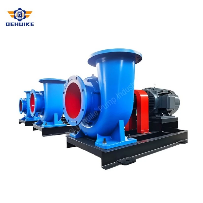
For an electric assembly, specify the available supply and required motor characteristics. The selected driver must suit the corrected pump duty and intended operating range. Starting or speed-control requirements should be reviewed with the electrical equipment supplier. A catalogue statement about motor poles does not identify every electrical interface, and 1450 r/min should not be described as a synchronous speed. Retain the confirmed motor record with the pump configuration so later changes can be assessed correctly.
For tractor drive, obtain an approved transmission arrangement matching the tractor output with the pump's required speed and power. Identify the mechanical connections, protection and installation instructions supplied. Tractor ownership alone does not demonstrate compatibility, and the listed pump speed cannot be applied directly to every power take-off. Compare the complete arrangement, including how it will be positioned and operated, before treating the tractor option as an economical substitute for a dedicated driver.
Equipment Characteristics | Judge Performance from the Selected Curve
The characteristics that matter in service are those established for the actual pump and duty. Capacity, head, absorbed power and suction requirement should be considered together, with applicable operating limits. A single rated point cannot establish the curve shape, low-flow behaviour or energy consumption throughout a season. The corrected Mixed Flow Water Pump record should therefore contain enough information to examine the expected operating cases and the drive arrangement selected to support them.
Manufacturing Process | Tie Production Activities to the Approved Construction
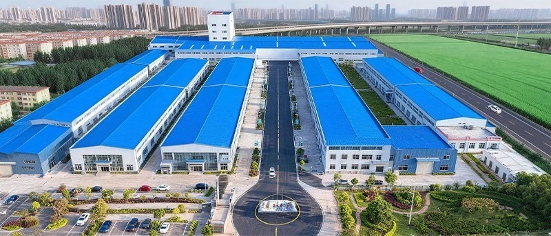
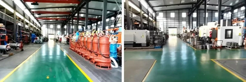
Manufacturing should begin from a released model and construction schedule. The corrected hydraulic selection, materials and drive interfaces need to agree before components are prepared. At Hebei Dehuike Pump Industry Co., Ltd., the proposed supply should identify the production and inspection information relevant to the order. Workshop-process descriptions can explain the manufacturing route, while acceptance depends on the agreed drawings, requirements and records for the actual equipment being delivered.
Applications | Base the Model Review on the Water Task
The following scenarios describe possible enquiry directions rather than authenticated installations or guaranteed outcomes. A Mixed Flow Water Pump should be assessed for each liquid and route using corrected performance information. Large-volume transfer does not remove the need to calculate required head, evaluate suction conditions and identify the drive arrangement. The project brief should distinguish measured inputs from assumptions and state where source or receiving conditions are expected to vary.
Engineering Questions | Selection Operation and Equipment Records
The questions below focus on information needed to assess a proposed assembly. They do not replace the manufacturer's operating instructions or the site's installation and safety procedures. Answers should be connected to the corrected model records before the equipment is ordered. This is especially important where a reference schedule includes power inconsistencies or where an application requires properties not established by the available product data.
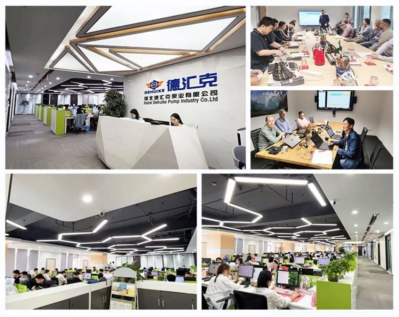
Corporate Manufacturing Strengths, Company Advantages, and Global Engineering Support
Engineering Selection FAQ, NPSH Calculations, and Maintenance Protocols
To assist consulting engineers, project managers, and procurement specialists in specifying and operating the Mixed Flow Water Pump, our technical department has compiled authoritative answers to frequent engineering inquiries.
Q1: How does a Mixed Flow Water Pump fundamentally differ from a standard end-suction centrifugal pump?
While both pumps share an end-suction volute casing format, their internal impellers and fluid velocity vectors differ completely. Standard end-suction centrifugal pumps utilize pure radial impellers where fluid enters axially and turns 90 degrees to discharge radially; this produces high head (30 m to 100+ m) but limited volumetric flow. A Mixed Flow Water Pump features a diagonal impeller whose vanes impart both centrifugal and axial velocity components, discharging fluid at an acute conical angle into a semi-axial volute. This geometry yields significantly higher flow capacities (250 m³/h to 580 m³/h in the DHW series) at moderate heads (20 m), accompanied by lower NPSHr, wider passage clearances, and superior efficiency at medium specific speeds.
Q2: How do I select among Tier 1 (DHW250-20), Tier 2 (DHW280-20 / DHW300-20), and Tier 3 (DHW580-20)?
Selection is determined by required volumetric duty and available discharge pipe sizing:
Choose Tier 1 (DHW250-20) if your required delivery is up to 250 m³/h, your discharge piping is 100 mm (4 inches), and equipment portability on light trailers or hand carts is your top operational priority.
Choose Tier 2 (DHW280-20 or DHW300-20) if your volumetric requirement ranges between 280 m³/h and 300 m³/h into 125 mm or 150 mm pipelines. Opt for the DHW280-20 when maximizing fuel economy with an 8 HP engine, or select the DHW300-20 with a 15 HP engine when extra pressure margin is needed for longer distribution lines.
Choose Tier 3 (DHW580-20) for high-capacity municipal flood drainage, regional irrigation schemes, or large industrial raw water intakes where moving 580 m³/h through 200 mm (8-inch) piping is required under the heavy-duty power of a 22 HP diesel engine.
Q3: What calculation protocol guarantees adequate Net Positive Suction Head (NPSH) margin to prevent cavitation?
To prevent destructive cavitation, the Net Positive Suction Head Available (NPSHa) in the installation must exceed the pump's Net Positive Suction Head Required (NPSHr) by a safety margin of at least 0.5 to 1.0 meter:
NPSHa = [ (100,000 * (Pa - Pv)) / (rho * g) ] + Hs - hf
Where Pa is local atmospheric pressure (bar / Pa), Pv is fluid vapor pressure at operating temperature (Pa), rho is fluid density (kg/m³), g is acceleration due to gravity (9.81 m/s²), Hs is static suction head (positive if liquid level is above pump center, negative if suction lift exists below center), and hf represents total friction and entrance losses in the suction piping. Across the DHW portfolio, NPSHr remains between 2.8 m and 3.8 m at 1450 r/min, allowing practical suction lifts up to 5.5 to 6.5 meters at sea level.
Q4: What are the primary advantages of pairing the pump with a tractor PTO rather than a dedicated diesel engine?
A tractor PTO configuration significantly reduces initial capital equipment expenditure for agricultural enterprises by leveraging existing farm tractors as mobile powerplants. Using an agricultural tractor PTO eliminates the need to maintain an additional stationary diesel engine, fuel system, and starting battery. The DHW tractor-coupled pump set features an integrated speed-matching gearbox or heavy-duty multi-strand V-belt drive that steps up standard 540 r/min or 1000 r/min tractor PTO output to the pump's optimal 1450 r/min operating speed. Farmers can drive the tractor to irrigation ditches, engage the PTO, complete pumping operations, and subsequently redeploy the tractor for tillage or transport tasks.
Q5: What is the recommended preventive maintenance schedule for bearing lubrication and gland packing?
Maintaining high operational reliability requires routine preventive attention:
Gland Packing: Inspect leakage daily during initial startup. A normal cooling leakage rate of 20 to 60 drops per minute must be maintained. Tighten gland follower nuts evenly by one-sixth of a turn if leakage becomes excessive. Never overtighten packing to zero leakage, as this causes rapid shaft sleeve scoring and thermal binding.
Bearing Lubrication: For grease-lubricated bearing brackets, replenish with lithium-complex EP2 grease every 500 operating hours. For oil-bath brackets, inspect oil level weekly via the sight glass and perform complete oil changes every 2,000 operating hours or seasonally.
Diesel Engine Servicing: Check engine oil and coolant levels daily before starting. Change engine oil and replace oil filters after the initial 50-hour break-in period, and every 250 operating hours thereafter. Inspect air filter elements frequently, especially in dusty agricultural environments.
Q6: Can the DHW Mixed Flow Water Pump handle water with suspended sand and solids?
Yes. Because the DHW mixed flow impeller features a wide-passage diagonal geometry rather than narrow radial channels, the pump handles suspended agricultural silt, river mud, and organic particles without clogging. For water containing highly abrasive quartz sand or mining tailings, Dehuike offers customized metallurgical options, including high-chromium white iron (Cr27) impellers and hardened shaft sleeves to resist abrasive erosion.
Q7: What are the international export packaging standards and standard commercial delivery terms?
All export DHW mixed flow pumps are thoroughly drained, coated internally with rust-preventive oil, and sealed at suction and discharge flanges with bolted heavy plastic blanking plates. Pump units are secured onto solid fumigated timber skids and encased in reinforced ISPM-15 compliant plywood sea-freight crates with moisture-barrier polyethylene wrap. We support international commercial trade terms under Incoterms 2020, offering FOB Chinese export port and CIF destination port agreements worldwide.

Hot Tags: mixed flow water pump, China mixed flow water pump manufacturers, suppliers, factory