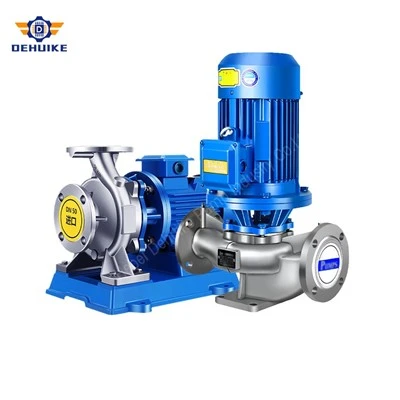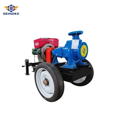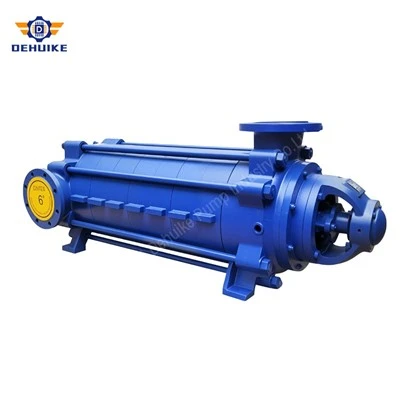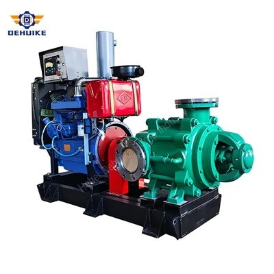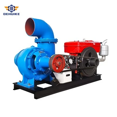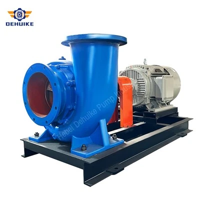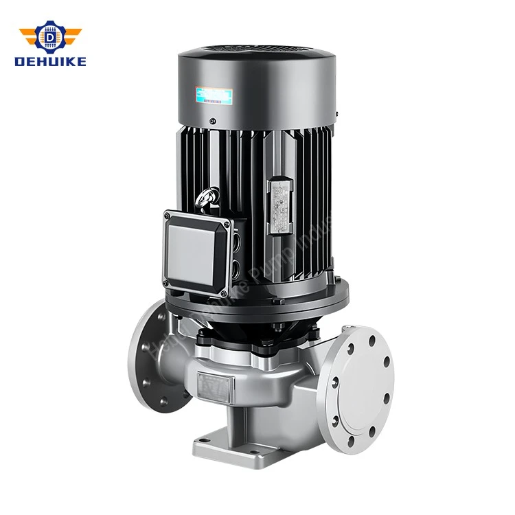
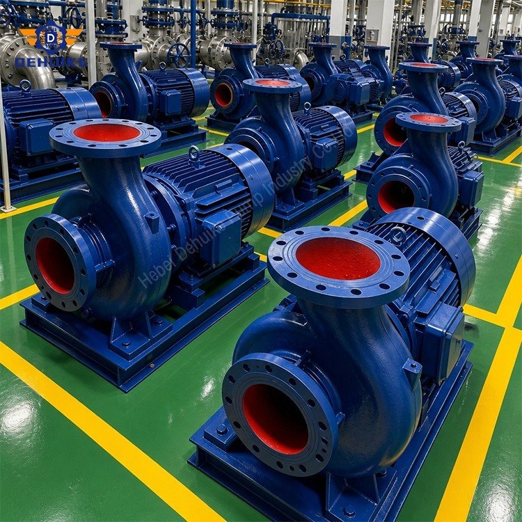
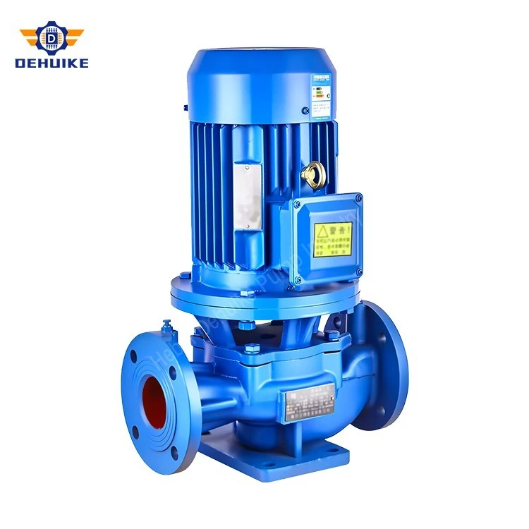
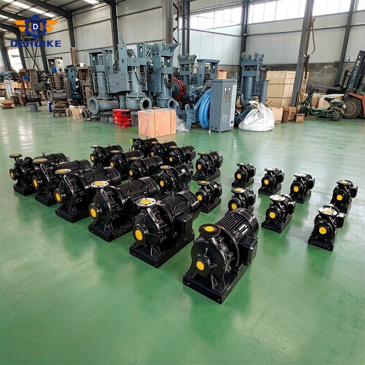
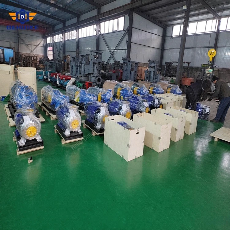
Hebei Dehuike Pump Industry Co., Ltd. is one of the most reliable manufacturers and suppliers of hvac inline circulation pump in China. With abundant experience, we are committed to providing high quality customized pumps with competitive price. Welcome to wholesale bulk hvac inline circulation pump for sale here from our factory. Also, pricelist is available.
Introduction - The Thermal Load Delivery Mission
The HVAC Circulation Mission: An HVAC inline circulation pump is a pipeline-mounted centrifugal machine whose engineering purpose is not to lift water, not to pressurize a network, and not to survive aggressive chemistry - but to move a measured volume of heat-carrying fluid through a closed hydronic loop at precisely the rate that matches the building's instantaneous thermal load. Installed in-line like a valve with coaxial suction and discharge nozzles, the HVAC inline circulation pump is the circulation heart of every modern chilled-water air-conditioning system, every hydronic heating distribution network, and every condenser-water cooling-tower loop in commercial and institutional buildings worldwide.
What distinguishes this machine from a general-purpose inline water pump is the demand profile it serves. A domestic booster pump runs against a pressure setpoint and reacts to faucet events. A boiler feed pump overcomes a fixed backpressure. An HVAC circulation pump serves a building whose thermal load swings from near-zero on a spring evening to full design capacity on a summer afternoon - a range of perhaps 10 percent to 100 percent of rated flow, with the pump riding that curve continuously, hour by hour, season after season. This load profile shapes every engineering decision: the pump must be efficient across a wide flow band (not just at a single duty point), stable at low turn-down (where recirculation and bearing loads shift), quiet enough to sit in a ceiling-space fan-coil room or a basement adjacent to occupied areas, and integrated with the building's control brain so that speed tracks demand rather than running flat-out against a throttling valve.
The DHK Pump HVAC inline circulation pump program covers the chilled-water and heating-loop duty range most commonly encountered in commercial and institutional construction. Rated flows span 8.8 m3/h for compact terminal-unit and fan-coil circuits up to 192 m3/h on large primary-loop distribution mains. Single-stage heads range from 12.5 meters for low-resistance AHU-coil circulation up to 55 meters for long secondary distribution runs. Motor ratings cover 0.75 kW to 37 kW at 2900 r/min (two-pole, high head density) and 1450 r/min (four-pole, acoustic-sensitive installations). Standard casing containment is 1.6 MPa; the fluid window runs from -10C to +80C for standard chilled and heating water, with high-temperature seal packages available for heating-loop duty above +80C.
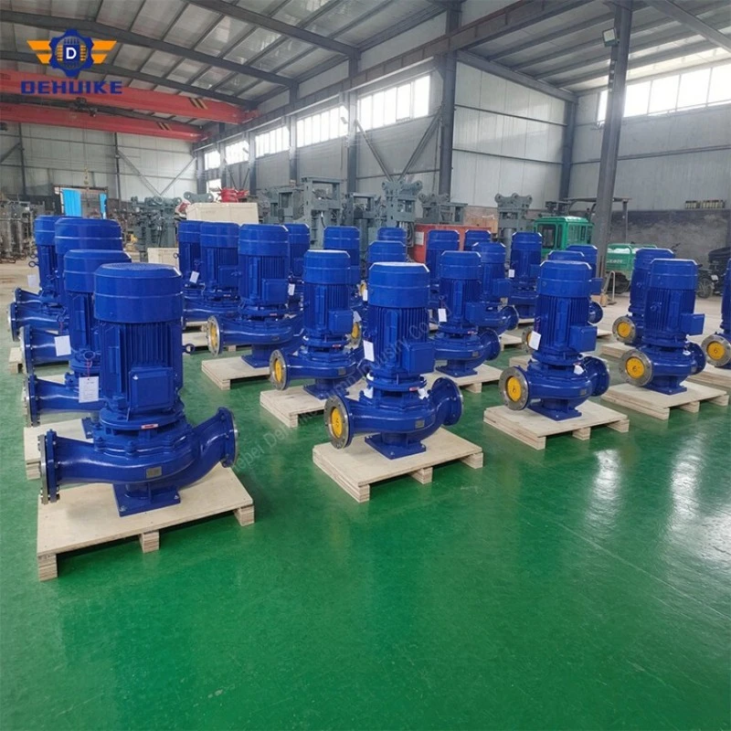
Chilled Water System Architecture & Loop Design
System Architecture Context: The HVAC inline circulation pump does not exist in isolation - it is an organ within a chilled-water or heating-water system whose architecture determines which pump goes where, at what flow, and at what head. The two dominant architectures in modern commercial construction are the primary-secondary loop and the variable-flow primary loop, and each has a distinct pump specification profile.
Primary-Secondary Loop Architecture
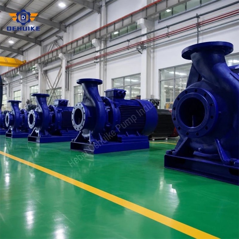
In the traditional primary-secondary design, a set of primary-loop HVAC inline circulation pumps moves chilled water from the centrifugal chiller evaporator through a low-loss common-pipe hydraulic separator at constant flow. This separator decouples the primary loop from the secondary distribution circuits hydraulically - pressure changes in one do not propagate to the other. Downstream of the common pipe, secondary-loop pumps - also HVAC inline circulation pumps, but variable-speed - circulate chilled water through the building's air-handling-unit coils, fan-coil units, and terminal heat exchangers, modulating speed to track zone demand. The in-line geometry is essential here: secondary-loop pumps are frequently installed in crowded ceiling mechanical rooms or wall-mounted distribution skids where every centimeter of floor space and every pipe elbow adds cost.
Variable-Flow Primary Loop Architecture
The newer variable-flow primary design eliminates the secondary pumping tier entirely. A single set of variable-speed HVAC inline circulation pumps serves both the chiller evaporator and the distribution circuit, with two-way control valves at each terminal unit throttling flow in response to zone demand. As valves close, the pump's variable-frequency drive decelerates to maintain the system differential-pressure setpoint, cutting both flow and energy. This architecture reduces total pump count, eliminates the secondary-loop electrical load, and simplifies the mechanical room - but it demands pumps that maintain stable hydraulic performance across a very wide flow range, from perhaps 10 percent of design flow at minimum load to 100 percent at design peak. Not every pump architecture handles that range gracefully; the impeller, seal, and bearing engineering of this program is validated across the full turn-down envelope.
Condenser Water & Cooling Tower Loops
A third common HVAC duty is the condenser-water circuit: circulating water between the chiller condenser and an external cooling tower. This loop operates at higher flow volumes (chiller condenser flow rates typically run 1.25 to 1.3 times the evaporator rate) and at lower heads (the circuit is short and the terminal resistance is modest). The HVAC inline circulation pump in condenser service sees near-ambient temperatures (27C to 35C supply, 32C to 35C return) but may be exposed to atmospheric contaminants, biological growth, and chemical treatment residues in the open cooling-tower circuit - a water chemistry that is benign to standard cast iron with appropriate inhibitor treatment.
Acoustic Engineering & Building Vibration Isolation
The Acoustic Budget: In occupied buildings, a pump is an uninvited acoustic guest. The HVAC inline circulation pump may sit in a basement mechanical room beneath a boardroom, in a ceiling plenum above a patient ward, or on a rooftop next to a penthouse apartment. Each of those placements imposes a noise and vibration budget on the pump that is as real as its hydraulic specification - and frequently more politically sensitive, because the complainant is not an engineer but an occupant who paid for quiet.
Vibration Generation, Transmission, and Isolation
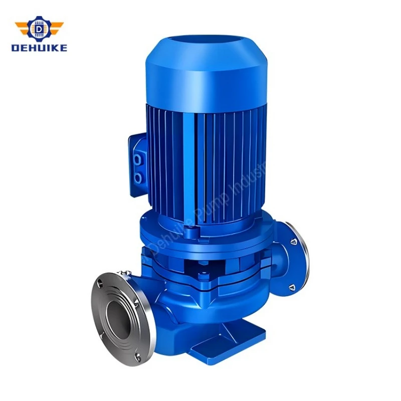
A rotating assembly spinning at 2900 r/min generates vibration energy at its running frequency (approximately 48 Hz on a 50 Hz supply) and at blade-pass frequencies above that. The close-coupled inline architecture is inherently quieter than baseplate-mounted alternatives: the rigid spigot alignment eliminates coupling misalignment vibrations, the short shaft resists whirling, and the ISO 1940 Grade G2.5 dynamic balancing of every impeller holds residual unbalance forces low enough that the pump's contribution to the building's structure-born noise stays well within typical HVAC acceptance limits. But the residual energy that does transmit through the pump casing feet into the pipework and the support structure must be managed at the installation level.
Casing Isolation: Spring isolators rated for the pump-plus-motor static weight, selected with a static deflection of 25 mm or greater to push the isolation system's natural frequency well below the pump running frequency. Neoprene pads under smaller units provide adequate isolation for ceiling-mounted fan-coil-circulation pumps at lower rotational speeds.
Pipe Decoupling: Flexible-connector hose or stainless-steel bellows on suction and discharge nozzles, interrupting the structural vibration path between pump and pipework. The connectors are sized for the pipe diameter, pressure rating, and temperature, and are installed with control rods that prevent over-extension under pressure.
Independent Support: Rigid pipe supports that carry dead weight independently of the pump, with neopberene isolation pads at the support-to-structure interface. The pump never serves as a pipe support - and pipes never transmit their structural loads into the pump casing.
Enclosure Option: Acoustic enclosure options for units installed adjacent to noise-sensitive occupied spaces, typically reducing radiated sound power by 8 to 12 dB(A) across the speech-frequency band.
Sound Power Targets and Building Code Compliance
Modern building codes and acoustic design guides (ASHRAE, AHRI, and local building code appendices) increasingly specify maximum pump sound-power levels in occupied spaces - particularly in hospitals, hotels, performing-arts venues, and residential towers. The DHK Pump HVAC inline circulation pump program is tested for sound power in accordance with ISO 3744 (precision-grade sound power determination using a reverberant-enclosure method). Standard models produce airborne sound pressure levels at 1 meter below 72 dB(A) across the rated duty range; the four-pole 1450 r/min executions - which drop the blade-pass frequency and the fundamental running frequency by half - are the specified option when the acoustic budget is tight. Combined with correct installation isolation, these levels deliver occupied-space sound levels that satisfy typical NC-35 to NC-40 room-criteria targets in offices, NC-30 in hospitality, and NC-25 in performing-arts venues.
Specifications & Technical Data
The duty ratings below are drawn from factory hydraulic test records for the HVAC inline circulation pump program, verified to ISO 9906:2012 Grade 2B acceptance. The models tabulated here span the range most commonly specified in commercial chilled-water and heating-water circulation: Table 1 covers compact and mid-range duties serving terminal-unit, fan-coil, and small AHU-coil circuits; Table 2 covers larger primary-loop and secondary-distribution duties. Enlarged-bore (I)-series models are featured where their higher efficiencies and lower NPSHr values make them the preferred HVAC selection.
Program envelope for HVAC specifiers: flows 8.8 to 192 m3/h per unit; heads 12.5 to 125 m; flange drilling DN40 through DN125 to DIN EN 1092 or ANSI patterns; casing containment certified at 1.6 MPa; standard fluid window -10C to +80C for chilled and heating water service, with high-temperature seal packages extending to +120C for heating-loop duty. Every model is available in A, B, and (on selected frames) C impeller trim variants for precise duty-point matching, and every unit is VFD-compatible from the factory.
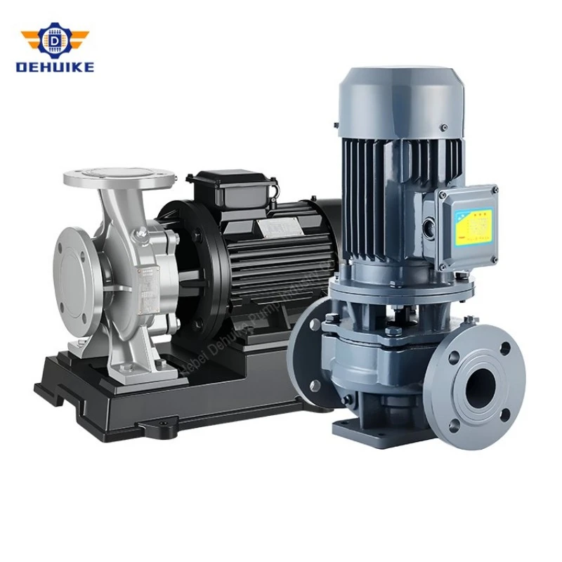
Table 1: Compact & Mid-Range HVAC Circulation Duties (DN40 to DN50, 2900 r/min)
|
Model |
Rated Flow (m3/h) |
Head (m) |
Efficiency (%) |
Speed (r/min) |
Motor (kW) |
NPSHr (m) |
|
40-100(I) |
12.5 |
12.5 |
62 |
2900 |
1.1 |
2.3 |
|
40-125(I) |
12.5 |
20.0 |
58 |
2900 |
1.5 |
2.3 |
|
40-125(I)A |
11.0 |
16.0 |
57 |
2900 |
1.1 |
2.3 |
|
50-100(I) |
25.0 |
12.5 |
69 |
2900 |
1.5 |
2.5 |
|
50-125(I) |
25.0 |
20.0 |
68 |
2900 |
3.0 |
2.5 |
|
50-160(I) |
25.0 |
32.0 |
63 |
2900 |
4.0 |
2.5 |
|
50-200(I) |
25.0 |
50.0 |
58 |
2900 |
7.5 |
2.5 |
|
50-250(I) |
25.0 |
80.0 |
50 |
2900 |
15.0 |
2.5 |
|
50-315(I) |
25.0 |
125.0 |
40 |
2900 |
30.0 |
2.5 |
|
50-315(I)A |
23.7 |
113.0 |
40 |
2900 |
22.0 |
2.5 |
Variable-Flow Control & Building Management System Integration
The Variable-Flow Imperative: Modern HVAC engineering has abandoned constant-speed, three-way-valve distribution in favor of variable-flow, two-way-valve architectures controlled by intelligent building management systems (BMS). In a variable-flow system, the HVAC inline circulation pump does not run at a fixed speed - it modulates its rotational velocity in real time to deliver exactly the flow the building's cooling or heating loads demand, no more and no less. This integration defines the pump's value in modern construction.
Differential-Pressure Control Logic
The BMS governs the HVAC inline circulation pump through a differential-pressure feedback loop. A pressure transducer mounted at the hydraulically most remote terminal unit (the farthest coil from the pump) reports actual line pressure to the BMS, which compares it against the setpoint and computes a correction signal using PID logic. The BMS sends this signal to the pump's variable-frequency drive, which adjusts motor speed - and therefore flow - to hold the remote differential pressure constant. As zone valves close in response to satisfied thermostats, the pump decelerates; as valves open, the pump accelerates. The result: the pump delivers the minimum flow required to satisfy the open valves, and no energy is wasted pushing water through a partially-closed throttling valve.
Affinity-Law Energy Economics
The centrifugal affinity laws quantify the savings. Flow is proportional to speed; head is proportional to the square of speed; shaft power is proportional to the cube of speed. Reducing pump speed from 100 percent to 60 percent reduces flow to 60 percent, head to 36 percent, and power consumption to 21.6 percent - a 78 percent energy reduction for a modestly reduced duty. Across a typical cooling season, where the average building load runs 40 to 60 percent of design, a VFD-controlled HVAC inline circulation pump consumes 40 to 60 percent less electrical energy than the same pump at fixed speed. This savings is the single most compelling economic case for variable-flow architecture and is the reason VFD integration is now standard rather than optional in commercial HVAC pumping.
Control Integration Architecture
- Analog Speed Reference: Hardwired: the BMS sends a 0-10V or 4-20mA analog speed-reference signal to the VFD, and the VFD returns a run/stop status and fault relay output. Simple, robust, and universal.
- Modbus RTU: Modbus RTU over RS-485: the BMS polls the VFD for speed, current, power, fault history, and running hours, and writes speed commands over the same bus. Richer data, still inexpensive to implement, and the industry-standard protocol for small-to-medium commercial installations.
- BACnet / LonWorks: BACnet or LonWorks: the native building-automation protocols, allowing the pump VFD to appear as a standard object in the BMS controller database with full scheduling, trending, and alarm management integration. The specified protocol for large campus, hospital, and government projects.
- Autonomous Drive PID: On-board PID loop in the VFD itself, with the pressure transducer wired directly to the drive. This architecture removes the BMS from the real-time control loop entirely - the pump self-regulates - and the BMS supervises only start/stop and setpoint changes. Preferred for smaller installations where BMS latency or reliability is a concern.
Seasonal Load Profiling & Pump Selection Methodology

Load-Profile-Driven Selection: Selecting an HVAC inline circulation pump from a catalog curve is straightforward; selecting the right pump for a real building across an entire year is an engineering exercise in load profiling. The pump that is correct at the summer design-day peak may be wrong for the 80 percent of the year when the building runs at partial load - and the pump that is efficient at partial load may not deliver the peak. The methodology below reconciles the two.
The Bin-Method Analysis
Professional HVAC pump selection begins not with a duty point but with a load-duration curve: the building's cooling or heating load plotted against the hours per year at each load level. The bin method (described in ASHRAE Handbook Fundamentals) divides the annual load profile into temperature bins - typically in 5C or 10C dry-bulb temperature increments - and counts the hours in each bin. The result is a curve that shows, for any percentage of design load, how many hours per year the building operates at or below that load. This curve is the economic basis for pump selection: it tells the engineer how many hours the pump will spend at full speed, at 60 percent speed, at 40 percent speed, and at minimum speed - and therefore what the annual energy consumption will be for a given pump and VFD combination.
Duty-Point vs. Best-Efficiency-Point Alignment
The pump's rated duty point (the flow and head the system demands at design load) should land on or near the pump's best efficiency point (BEP) at full speed. But the pump also spends the majority of its operating hours at turn-down speeds where the affinity laws shift the operating point along the system curve - and the pump's efficiency at those turn-down points matters as much as the peak efficiency. The HVAC inline circulation pump program's impeller geometry is designed for a broad efficiency island, not a narrow efficiency peak, precisely so that the efficiency at 60-percent speed remains acceptable. When comparing pump selections, examine the efficiency curve across the 40-percent to 100-percent speed range - not just the single BEP figure.
Minimum-Flow and Turn-Down Constraints
Every centrifugal pump has a minimum continuous stable flow (MCSF) - the flow below which internal recirculation, bearing loads, and temperature rise become damaging. For the program's standard inline models, MCSF is typically 25 to 35 percent of BEP flow at full speed. With a VFD, the pump can operate at lower absolute flows because the entire curve shifts down with speed - but the MCSF ratio remains roughly constant, and operating below it for extended periods causes low-flow recirculation noise, seal face distress from reduced flush, and potential bearing damage from hydraulic unbalance. The BMS control strategy should include a minimum-speed floor (commonly 30 Hz or 60 percent of rated speed on a 50 Hz supply) to prevent operation below the stable flow envelope.
Hydronic Balancing & Commissioning Protocol
Balancing as Commissioning: A pump that is correctly selected and properly integrated will still underperform if the distribution system it serves is out of balance. Hydronic balancing - the process of adjusting each terminal circuit's flow to match its design allocation - is the commissioning step that determines whether the building achieves its design comfort, or whether the pump over-delivers to some zones and starves others. The protocol below covers the balancing sequence for an HVAC inline circulation pump serving a variable-flow hydronic distribution.
Pre-Balancing Preparation
- System Fill & Treatment: Verify that the entire hydronic loop is filled, vented at all high points, and chemically treated to the specified inhibitor levels. Air in the distribution system causes flow measurement errors and can damage the pump's mechanical seal through dry-run intermittency. Install and verify the operation of all air-separation devices and expansion tanks before beginning balancing.
- Full-Open Verification: All two-way control valves are commanded to 100-percent open position by the BMS, and all manual balancing valves are set to their initial (pre-calculated) positions. The pump is started at full speed against the fully-open distribution circuit, and the design flow and head are verified against the pump's certified performance curve.
Proportional Balancing Sequence
Balancing proceeds from the hydraulically most remote terminal circuit toward the pump, using calibrated flow-measurement devices (ultrasonic flow meters or differential-pressure readouts across circuit balancing valves). Each circuit's balancing valve is adjusted so that the measured flow matches the design flow within a 10-percent tolerance. The sequence is: most-remote circuit first, then the next most-remote, working inward toward the pump. After each circuit is set, the previously-balanced circuits are re-checked - because adjusting one circuit changes the pressure available to all others (the hydraulic coupling effect). Two to three passes through the circuit sequence typically converge the system to within 10 percent of design flow at every terminal.
Variable-Flow System Commissioning
Once proportional balancing is complete at full speed, the variable-flow commissioning begins. The BMS commands the most-remote transducer as the active control point, and the system is run at progressively lower speeds (100, 80, 60, 40 percent) while the differential-pressure setpoint is verified at each speed. The setpoint is tuned so that the most remote terminal receives adequate flow at the minimum operating speed - the 'minimum-differential-pressure setpoint' - ensuring that even at turn-down, the farthest coil does not starve. The minimum-speed floor (typically 30 Hz) is confirmed and entered into the VFD parameters. Finally, a load-shedding test simulates valve closures across multiple zones to confirm the pump decelerates smoothly without hunting, oscillation, or cavitation.
Commercial Procurement & Global Engineering Support
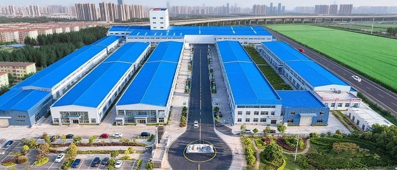
Manufacturer Profile: Hebei Dehuike Pump Industry Co., Ltd. (DHK Pump) has specialized in industrial fluid machinery for more than 30 years. From a 8,000+ m2 production campus - precision CNC machining cells, automated hydraulic test stands with integrated sound-power measurement capability, and dedicated VFD-integration testing bays - supported by 900+ qualified supply partners, our HVAC inline circulation pumps serve commercial building projects, district energy networks, and institutional mechanical systems across more than 50 countries.
Warranty & Certification: Each HVAC inline circulation pump carries a 24-month (two-year) mechanical warranty covering materials and factory workmanship (wear parts excluded per industry practice), with ISO 9906 Grade 2B hydraulic test certification and optional sound-power test data per unit.
Commercial Terms: Export quotations follow Incoterms 2020 - FOB or CIF to the destination port - supported by EN 10204 3.1 material certification, hydraulic performance curves, and VFD integration documentation in the submittal dossier.
Logistics: Freight moves by air for urgent consignments in the 50-500 kg range, and by ocean for volume orders above 500 kg, crated to ISPM 15 standard with VCI moisture-barrier protection.
HVAC Pump Engineering FAQ
The questions below represent the recurring specification and operational inquiries the engineering desk receives from HVAC consulting engineers, mechanical contractors, and building facilities managers.
Q1 - Speed Selection | How do I select between a two-pole (2900 r/min) and a four-pole (1450 r/min) pump for the same duty?
When the hydraulic duty can be met by either speed, the four-pole option is the acoustic-sensitive choice - it halves the fundamental rotational frequency and the blade-pass frequency, dropping both by approximately 6 dB(A) in radiated sound power. The trade-off is physical size: a four-pole motor and impeller are larger for the same duty, and the four-pole pump costs slightly more. Specify two-pole where the mechanical room is acoustically isolated from occupied space; specify four-pole where the pump sits beneath or adjacent to sensitive areas.
Q2 - Minimum Speed Floor | What is the minimum-speed floor for a VFD-controlled HVAC pump, and why does it matter?
The recommended minimum operating speed is 30 Hz (60 percent of a 50 Hz rated speed). Below this floor, the impeller's internal flow field destabilizes - recirculation at the impeller inlet creates noise, the mechanical seal's flush flow (if Plan 11) may diminish below the rate needed for cooling, and the motor's integral cooling fan loses airflow. The BMS should be programmed to never command the pump below this floor; if the load truly demands less flow, the solution is staging (stopping one pump in a parallel set) rather than running a single pump below its stable turn-down.
Q3 - Changeover Systems | Can a single HVAC inline circulation pump serve both cooling and heating modes?
Yes - in a changeover system where the same piping loop carries chilled water in summer and hot water in winter. The pump must be specified for the more demanding of the two duties (typically the higher-viscosity, higher-temperature heating mode if the hot-water temperature exceeds +80C, requiring the high-temperature seal package). The control strategy must account for the different flow requirements of cooling vs. heating - heating loops often run at lower flow and higher temperature differential than cooling loops - and the VFD setpoint may need seasonal adjustment.
Q4 - Pump Count & Redundancy | How many pumps should the system have - one, two, or three?
The industry-standard answer is N+1: the number of duty pumps (N) required to meet design load, plus one standby. In a typical commercial building, this means two pumps (one duty, one standby) on smaller secondary loops, and three pumps (two duty, one standby) on larger primary loops. The pumps rotate lead/lag duty automatically by runtime hours, and the standby starts on demand if a duty pump fails or if load exceeds single-pump capacity. Specifying N without the +1 leaves the building without cooling when a single pump trips - an unacceptable risk in most commercial and institutional contexts.
Q5 - Water Treatment & Warranty | What water-treatment requirements affect the pump's warranty and
The standard warranty requires the circulated water to be treated with an appropriate corrosion inhibitor (commonly sodium nitrite, molybdate, or a phosphate-based compound for closed-loop systems) and maintained within the specified pH and conductivity ranges. Untreated water in a closed hydronic loop causes corrosion that fouls pump internals, erodes seal faces, and invalidates the warranty. The water-treatment specification is part of the mechanical design, not an afterthought, and water samples should be tested at commissioning and at each seasonal changeover.
Q6 - Service Life Economics | How long should an HVAC inline circulation pump last?
In a properly specified, properly balanced, properly treated closed-loop system, the pump casing outlasts the building; the life-limiting components are the mechanical seal (15,000 to 20,000 operating hours typical), the motor bearings (40,000 to 50,000 L10h hours), and the VFD (electronic component life, typically 8 to 12 years to first failure). With routine preventive maintenance - seal replacement at the recommended interval, annual bearing greasing, and VFD firmware checks - the pump provides 15 to 20 years of reliable service before major refurbishment. The economics are straightforward: in a system that runs 4,000 hours per year, the annual energy cost exceeds the pump's purchase price within two to three years - which is why efficiency and VFD integration matter more than capital cost over the service life.

Hot Tags: hvac inline circulation pump, China hvac inline circulation pump manufacturers, suppliers, factory