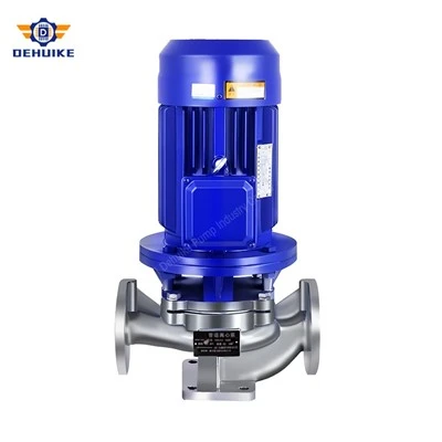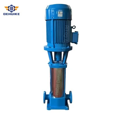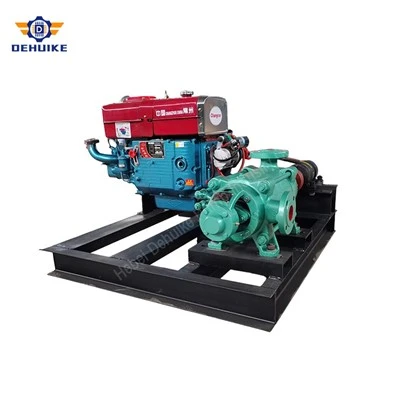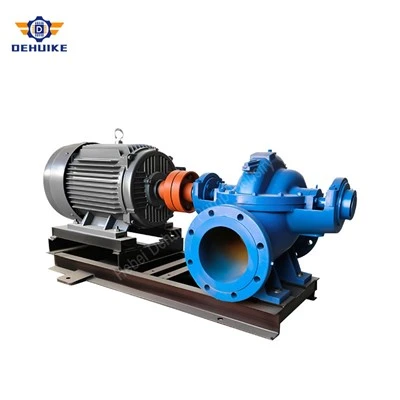
Hebei Dehuike Pump Industry Co., Ltd. is one of the most reliable manufacturers and suppliers of is industrial water transfer pump in China. With abundant experience, we are committed to providing high quality customized pumps with competitive price. Welcome to wholesale bulk is industrial water transfer pump for sale here from our factory. Also, pricelist is available.
Introduction | Keep Production Water Moving Between Plant Services
A factory water system connects storage, treatment, production and heat-removal equipment. Each part needs a dependable share of the available supply, often at different times during a shift. This IS range uses a horizontal end-suction centrifugal arrangement for water duties suited to its construction. Its selection follows the required delivery through the plant: how much water is needed, what resistance the route presents and which operating conditions the installation will encounter.
This range brings several hydraulic choices into one product comparison. The table separates unsuffixed models from A and B variants, with each entry carrying its own capacity, head, speed and motor reference. That makes it possible to examine a lower-head alternative without losing sight of the water volume it delivers. The model should be selected for the work being done; motor capacity and pipe diameter provide supporting information rather than a substitute for the hydraulic requirement.
Water quality defines the construction question. A treated utility supply, a cooling circuit and a tank-transfer line can differ in temperature and composition even when all three are called water systems. Provide the conditions expected over the working cycle, including any suspended contamination. Materials and sealing can then be related to the liquid. Hot operation needs an applicable temperature-and-pressure rating for the assembled pump, including the components at the shaft passage.
The product information below follows the questions that arise as a pump moves from a proposed duty into plant service. It explains the arrangement, the differences between listed references and the factors that affect installation and upkeep. The aim is a practical match between the selected pump and its receiving system. That match includes the physical assembly and operating routine, as well as a curve that meets the required water delivery.
Features / Equipment Characteristics | Useful Details for the Installed Assembly
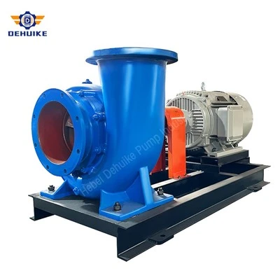
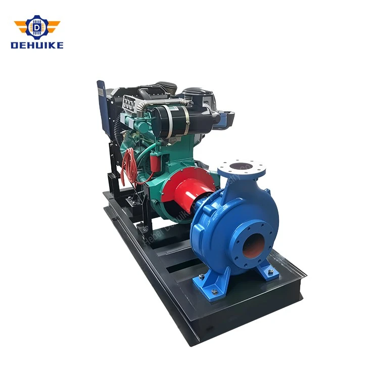
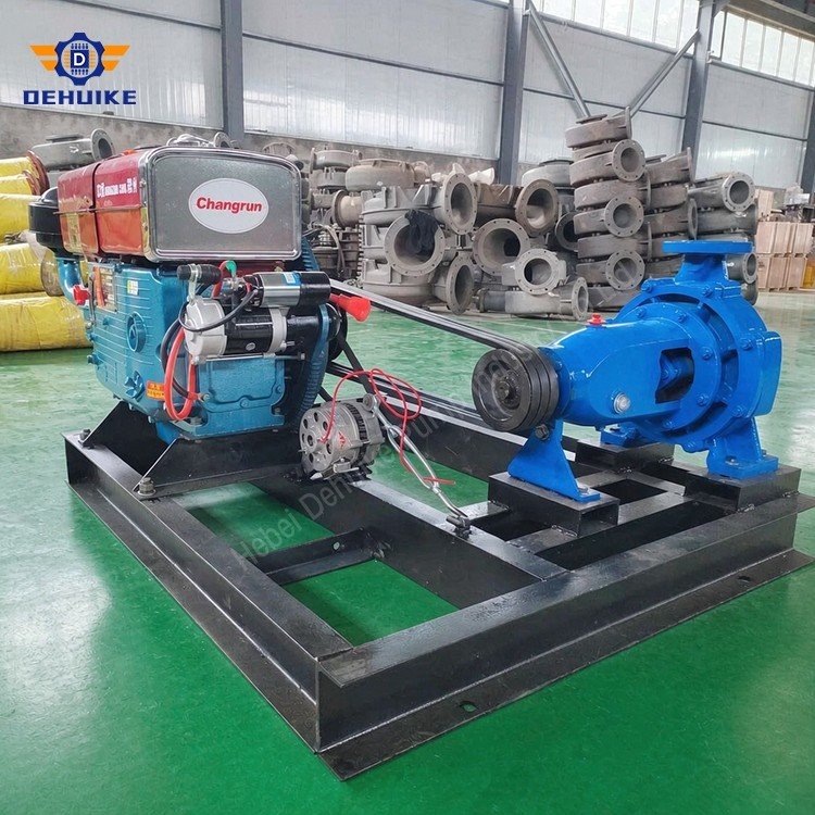
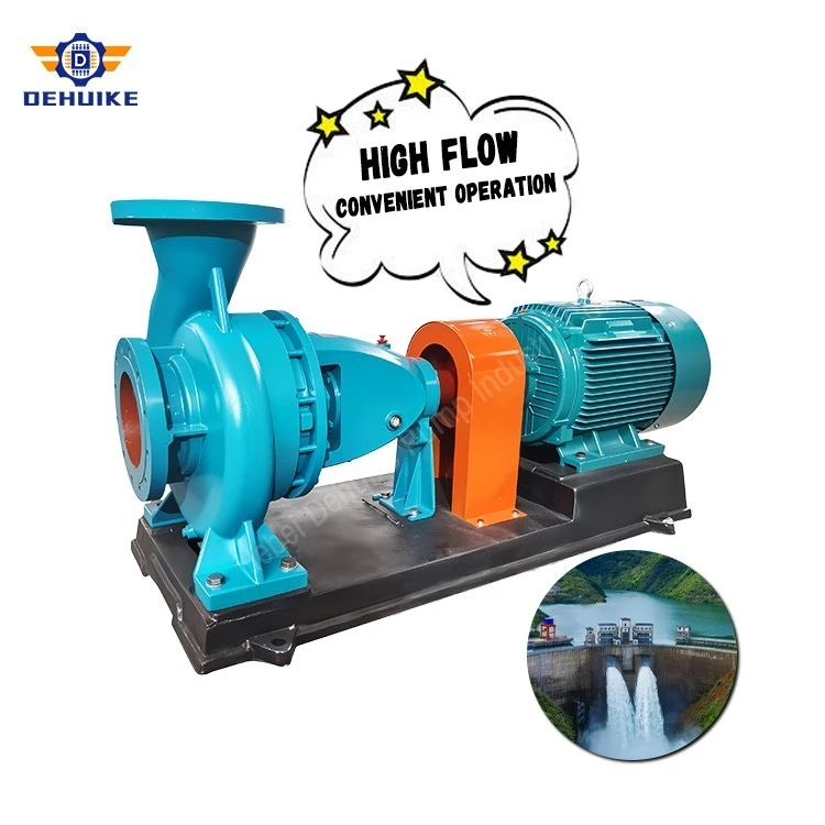
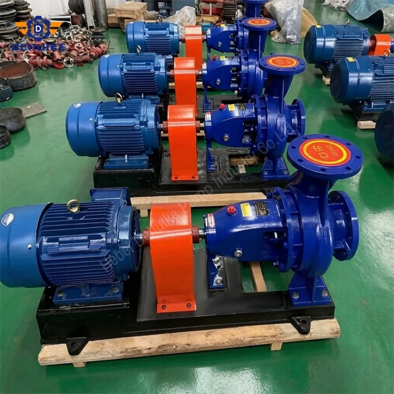
Horizontal mounting places the pump and driver in a layout that can be coordinated with a base and surrounding pipework. The axial inlet faces the approaching suction route, while the described discharge rises from the casing. This arrangement gives the designer defined connection positions around which to plan the installation. Room for the motor, coupling, seal area and component withdrawal should appear in that layout, so the finished assembly remains accessible after the pump room is complete.
Several related duty references help avoid treating every transfer line as the same job. A short route between tanks may require a different head from equipment supply through restrictive branches. A or B variants offer additional listed combinations within particular model families. Their relevance comes from the conditions on their curves, including the expected variations in service. A suffix is useful identification, while the actual hydraulic information determines whether the option meets the task.
Rear access is a maintenance consideration where the offered construction uses a back-pull-out assembly. It allows the service procedure to be organized around withdrawal from the casing rather than removal of the entire connected pump. Coupling type and available space affect how that work is carried out. Providing the necessary clearance during layout design preserves the benefit; an obstructing cable tray or adjacent machine can otherwise make the intended removal path unusable.
The suction requirement is listed beside the other performance data so inlet conditions can be considered early. Those values must be read for the relevant model and condition. Source pressure, water level, liquid temperature and the approach losses establish what the installation can provide. Comparing the available condition with the pump requirement is more informative than describing an inlet as low suction or assigning a general lift capability to every size in the range.
A clearly identified assembly also supports future servicing. The ordered model and hydraulic variant should lead to the correct drawings and component references. The driver, sealing equipment and any ancillary connections belong in that same record. This makes a later parts enquiry more precise and helps the maintenance team plan the equipment needed for access. A nominal family name alone is insufficient when different constructions or earlier modifications may exist at one site.
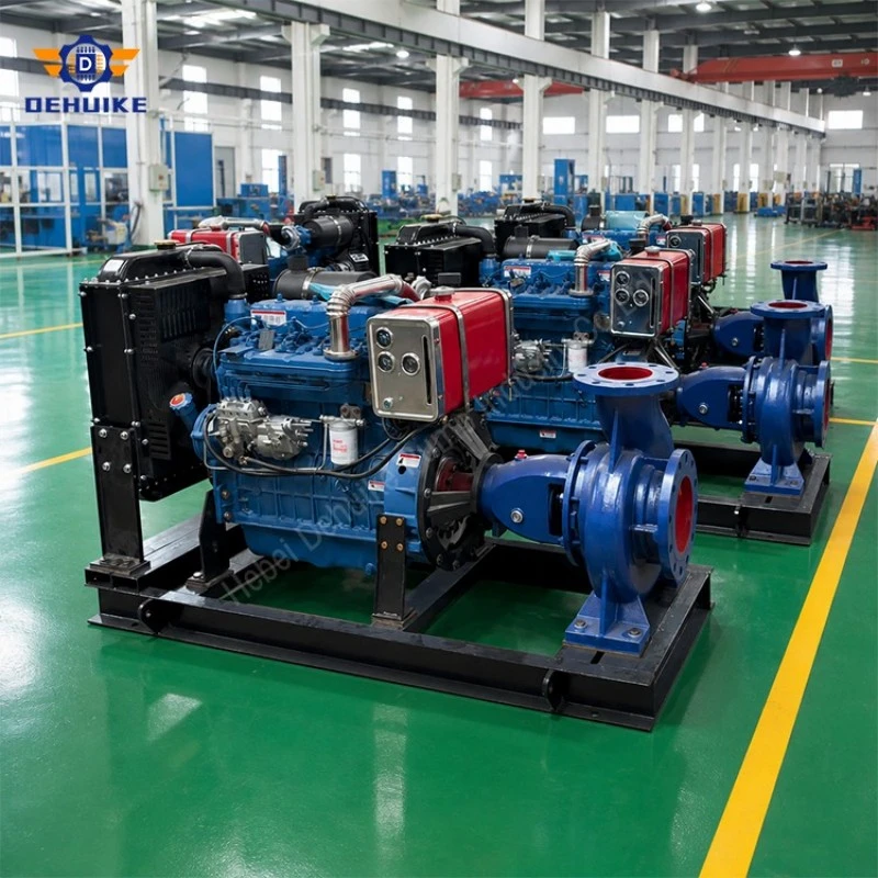
Product Details | Components Along the Water and Drive Paths
At the inlet, water approaches the impeller eye. Rotation transfers energy to the flow, and the casing leads the outgoing stream towards the discharge. The head produced and capacity delivered are linked to the speed and hydraulic configuration. Once connected to a plant, the operating point also reflects the network. A change in route, valve position or receiving-equipment resistance can therefore change delivery without any alteration to the pump's model or internal components.
The casing carries the main fluid connections and forms the principal pressure boundary. Its material, joint arrangement and applicable pressure conditions belong to the chosen construction. Where renewable internal wearing items are fitted, their identity and inspection criteria form part of the service information. The casing drawing is also important to installation: it establishes the connection locations and support geometry that the piping and foundation must accommodate, beyond the nominal nozzle diameters shown in a table.
Mechanical drive passes through the shaft to the impeller. Sleeves and related components, where included, provide serviceable interfaces around the shaft passage. The offered shaft and sleeve grades should be associated with the particular assembly rather than inferred from a general series description. For repair work, their fit with the impeller, seal and bearings matters as much as the material designation. Use the delivered component references when identifying replacements after an overhaul.
The bearing housing supports the rotating parts and provides the specified lubrication arrangement. Access to it is needed for the observations and servicing described in the operating instructions. Its condition is influenced by the installation and working duty, including alignment and contamination control. A bearing calculation can support design review under stated assumptions, but operating experience at a plant depends on the complete arrangement. The relevant maintenance instructions should remain available beside the equipment record.
Sealing controls the passage where the shaft leaves the water side. The arrangement may require different attention depending on whether packing or a mechanical seal is supplied. Auxiliary piping, if needed, should have a defined source and destination and be included in the package boundary. The practical questions for the owner are what is fitted, which services must be available and how the specified arrangement is operated. A general seal-plan label cannot answer all three.
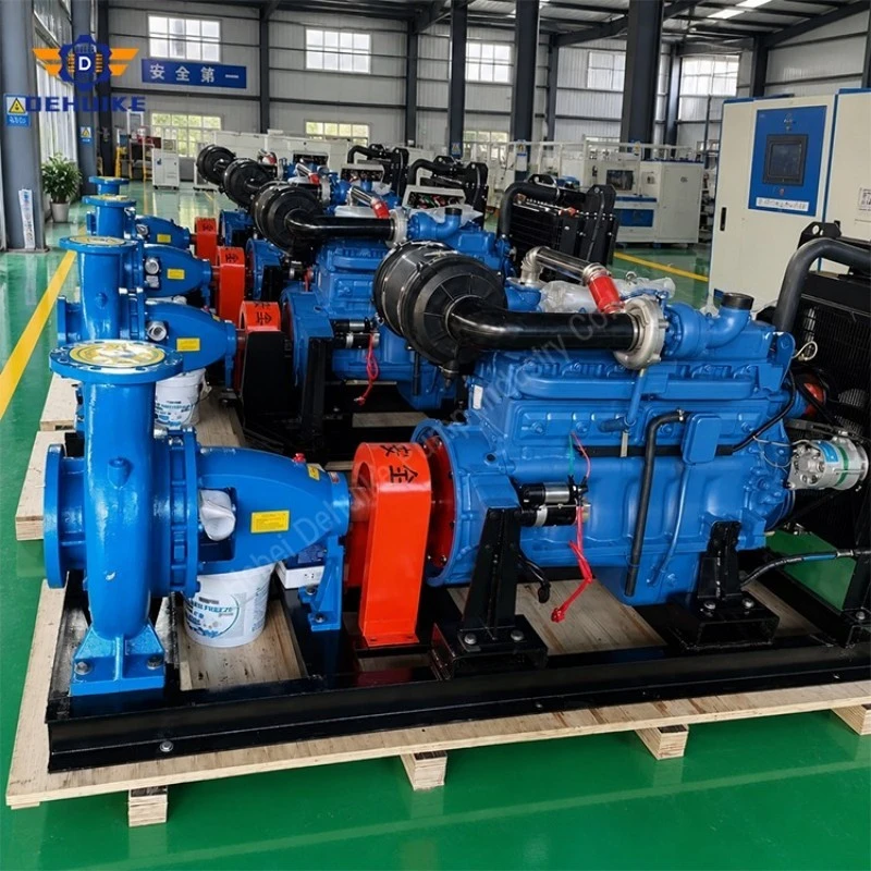
Specifications and Technical Data Matrix | Read Each Model as One Hydraulic Record
Each row below keeps the speed, flow points and corresponding heads together. The first capacity pairs with the first head, the middle with the middle and the last with the last. Efficiency, NPSHr and motor entries remain attached to that reference. This is a screening schedule rather than a replacement for the full selected curve. It does not assign a minimum continuous flow or a maximum permissible operating point merely by listing three conditions.
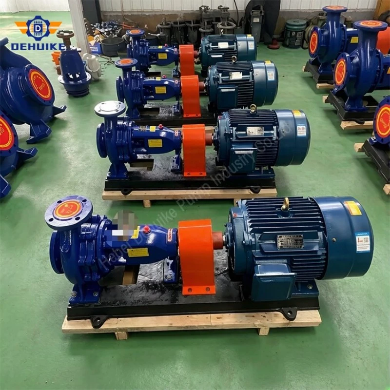
Our Advantages | Selection Clarity and Serviceable Equipment Information
Related IS references give the project team a way to compare different transfer conditions while keeping the essential data in one place. Engineering can follow the curve and construction, purchasing can identify the package being priced and maintenance can see which assembly will arrive. The benefit is a coordinated selection rather than an isolated pump name. It is strongest when the offered model is linked to a defined water task and the installation information needed to use it.
Operating cost becomes easier to discuss when it is related to useful delivery. Compare electrical input with the quantity of water moved under documented conditions, and account for changing load where the plant has several working cases. The highest efficiency appearing in this schedule is 81.0%, attached to its individual reference. It cannot represent every model at every flow. For a purchase-electricity comparison, the driver and control arrangement also need to be included in the calculation boundary.
Maintenance preparation can be built around the parts and access provided in the selected assembly. Identify wearing components and their order references, establish the withdrawal route where applicable and retain the operating instructions. This allows the plant to arrange tools, handling equipment and appropriate spares before an intervention is needed. A controlled assembly record is particularly useful where several similar pumps operate on site or equipment has been modified during previous repair work.
Replacement work benefits from a measured interface comparison before the shutdown. Check inlet and outlet positions, mounting geometry, shaft height, drive connection and space around the assembly. An applicable dimensional standard may help organize that review, but the offered drawing and site measurements establish the actual fit. Known adaptations can then be included in the shutdown plan, reducing uncertainty about work on pipes or foundations once the existing unit has been removed.
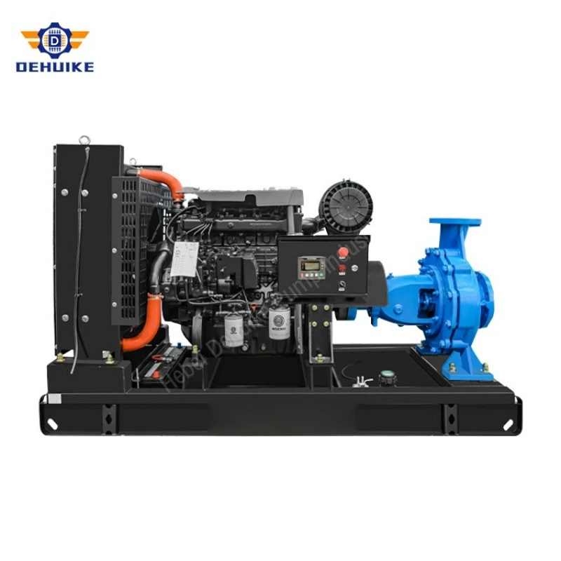
Application | Separate the Water Task from the Industry Label
The same plant can contain several water services with very different conditions. Storage transfer, wash-water supply and cooling circulation should each have a defined duty and liquid description. The IS range can be assessed for suitable services of this kind, using the relevant curve and construction. Industry names help explain where the equipment will be installed, while the water properties and hydraulic requirement establish whether the proposed assembly is appropriate for the specific task.
In refinery and chemical-site utilities, the water service should be distinguished from the adjacent process. A cooling circuit needs sufficient delivery through its connected users and a construction suitable for the treatment and temperature involved. The relevant head includes the network and equipment conditions of that circuit. Suitability for that water does not establish compatibility with chemicals handled elsewhere on the site. The enquiry should identify the stream and all operating cases on which the selection is to be based.
Automotive facilities may distribute water to equipment users that start and stop in different combinations. Describe those demand cases and the pressure required where water reaches each receiving group. The proposed pump and control method can then be reviewed as a working arrangement. A different process liquid within the same factory requires its own assessment. In particular, a description of general plant-water supply should not be extended automatically to immersion baths or other treated process streams.
Textile operations may require movement of softened water, supply to washing stages or transfer between utility tanks. State the expected temperatures and chemical additions rather than assuming the liquid remains equivalent to untreated clean water. Where hot operation is required, the offered assembly needs the relevant material, seal and pressure-temperature information. Process effluent and dye-bearing streams are separate duties. Keeping those distinctions visible gives the supplier a meaningful water task to evaluate.
Paper-production sites should identify whether the enquiry concerns suitable utility water or liquid containing fibres and other process contaminants. For an intake from a changing source, seasonal level and water-condition information belong in the selection data. Any filtration provision should also be described. A pump chosen from a clean-water schedule cannot be assumed to accept an unspecified fibre content, and a favourable source level does not establish delivery throughout the range of expected intake conditions.
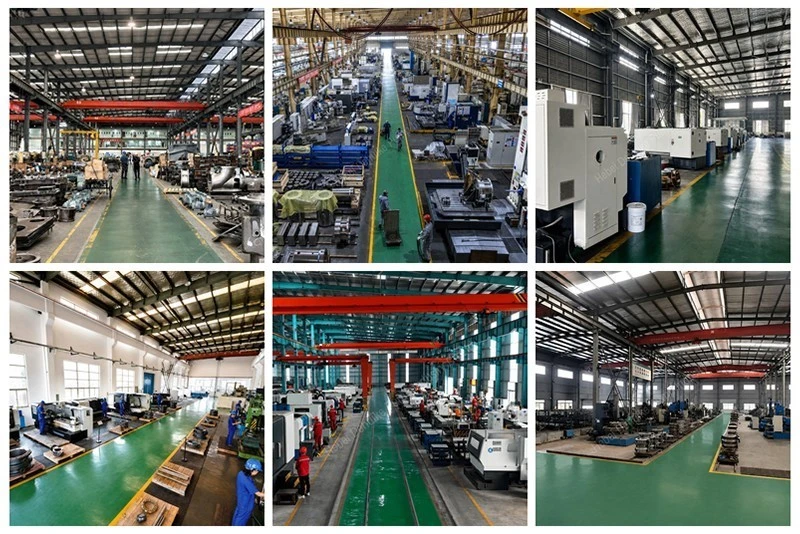
Quality Assurance and Factory Verification | Connect Acceptance to the Delivered Pump
The acceptance plan should begin with the equipment and construction approved for the order. Identify the model, hydraulic variant, driver and documents against which the supply will be checked. Company quality-system evidence can support supplier qualification where required, while inspection records address the relevant equipment and components. Keeping those roles distinct helps the buyer ask for useful evidence and avoids treating a broad certification claim as proof of every feature on an individual pump.
Pressure-boundary verification needs an agreed procedure for the applicable construction. Define the test conditions, acceptance criteria and identification to appear in the record. The pressure used for proof testing has a different purpose from the permitted service pressure, and neither alone establishes the transient behaviour of the installed network. If witnessing or additional documentation is required, include it in the inspection scope before manufacture. The result should describe what was actually tested and accepted.
Hydraulic testing should relate to the selected performance requirement and use a defined method and tolerance. The record needs the relevant speed, liquid and assembly identity so the buyer can interpret its scope. Clarify whether the information concerns the individual unit or a reference configuration. Where additional verification such as NPSH testing is needed, specify it separately. A table of nominal flow and head values does not demonstrate that every possible test is included with every order.
Running observations should also have a clear context. Vibration and temperature readings, where required for acceptance, need measurement locations, operating conditions and agreed limits. After installation, foundation support, connections and the actual duty can influence the readings. Commissioning provides an opportunity to establish a site reference using a repeatable method. Later changes can then be investigated against documented service conditions instead of being judged solely against a factory result from another arrangement.
Handover documents should allow the owner to identify and operate the assembly supplied. Include the agreed drawings, instructions, reports and component evidence, with accepted changes recorded in the final revision. Certificates should have a clear scope and connection to the relevant items. The maintenance team needs a usable final record rather than a mixture of superseded submissions. Correct identification also helps the supplier answer later enquiries about wearing parts, seals and other replacement components.
Our Service Experience and Markets | Turn the Enquiry into a Defined Supply
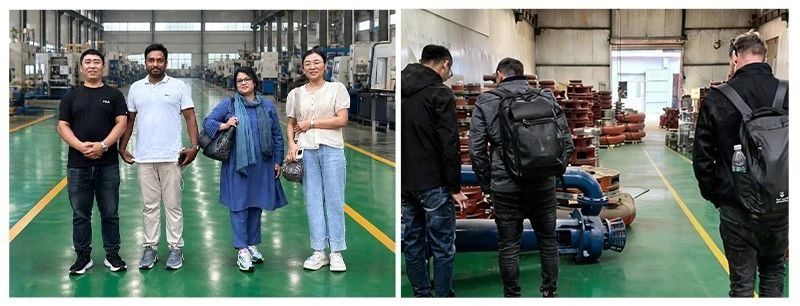
When requesting an IS proposal from Hebei Dehuike Pump Industry Co., Ltd., describe the required delivery and the conditions at both ends of the route. Add liquid information, electrical supply and known installation constraints. These inputs allow a discussion about an identified model and construction rather than an open-ended request for a water pump. The quotation should connect the proposed equipment with the duty considered and make any assumptions or outstanding decisions visible to the buyer.
Establish the package boundary before comparing prices. A bare-pump supply differs from an assembly with driver, base, coupling and guard. Instruments, valves, controls and auxiliary connections should be itemized where included. The drawing should show customer interfaces and service space for the offered arrangement. Also assign the work that remains at the destination, including installation checks and final alignment. That distinction lets the owner plan site completion without assuming every necessary item arrives on the skid.
Delivery commitments should describe the actual order. Model availability, quantity, bought-in components, drawing approval and requested inspections can affect release. Obtain the applicable schedule and identify information needed from the project team to maintain it. Manufacturing-profile information may be relevant to qualification, with supporting evidence where it is relied upon. It does not replace an order-specific delivery plan or establish that every configuration can be supplied within one standard lead time.
For overseas projects, address destination requirements during quotation. Electrical conditions, documentation language and conformity evidence can influence the assembly and approval work. Request comparable references where these are needed for supplier evaluation, and discuss the support available for the actual installation location. Broad export claims should not be treated as a promise of local stock or attendance. The project should know which assistance is included and which services would need a separate arrangement.
The accepted offer should state warranty coverage and the engineering support included. Record the term, start event, exclusions and claim procedure, with the treatment of purchased components made clear. The motor specification should use the site's required voltage, frequency and enclosure information. Any specialist approval or attendance should have a defined scope. This gives the customer a commercial record that can be read alongside the technical schedule when the equipment is received or support is needed later.
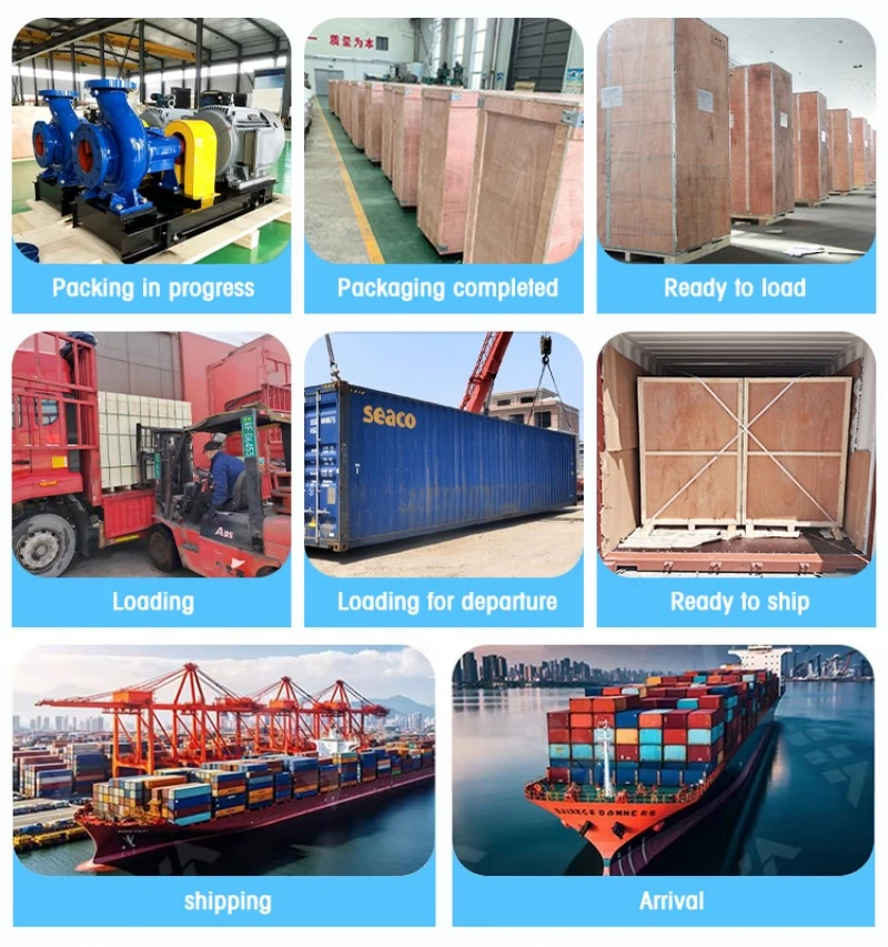
Shipping preparation should follow the completed assembly and transport plan. Agree the preservation needed before installation, identify separately packed components and obtain packed dimensions and mass for handling. The trade term and named delivery place belong in the contract, along with relevant document responsibilities. The receiving team can then coordinate storage and installation using consignment-specific information. A general freight weight threshold cannot determine the most suitable route for every pump order.
Engineering FAQ: Technical Sizing and Operating Guidelines for Industrial Transfer Pumps
Q1: What are the engineering criteria for operating two IS industrial water transfer pumps in parallel on a shared discharge header?
When operating centrifugal pumps in parallel, both units must have identical or closely matched shut-off heads to prevent the stronger pump from backing up fluid through the weaker unit. The combined system operating point occurs where the combined H-Q curve (adding flow rates at each head level) intersects the piping system resistance curve. Each pump discharge line must be fitted with a fast-closing non-slam check valve to prevent reverse rotation during single-pump tripping, and a minimum-flow bypass line should be provided if system demand can drop below 30% of rated flow.
Q2: How does water hammer occur in long industrial water transfer lines, and how should it be mitigated?
Water hammer is a hydraulic pressure surge created when the kinetic energy of flowing water is rapidly converted into pressure waves following sudden pump shut-down or rapid valve closure. In long industrial transfer lines, surge pressures can exceed pipe burst ratings. Mitigation measures include: installing slow-closing motorized control valves, incorporating air-release and vacuum-relief valves at pipeline high points, adding a hydro-pneumatic surge bladder vessel on the discharge manifold, and ensuring pump check valves close before flow reversal begins.
Q3: Which mechanical seal flush plan (API Plan 11 vs. Plan 13) is recommended for industrial cooling tower water circulation?
For clean cooling water with temperatures below 60°C, API Plan 11 (recirculation from pump discharge nozzle through an orifice to the seal chamber) provides continuous seal face lubrication and heat dissipation. However, if cooling tower water contains suspended dust, silt, or scaling minerals, an in-line cyclone abrasive separator should be added to Plan 11, routing clean fluid to the seal faces while returning solids to the pump suction. For dirty effluent or slurry-adjacent clean water, an external clean water flush (API Plan 32) is recommended.
Q4: What is the minimum recommended continuous operating flow (MCOF) for the IS series to prevent internal thermal buildup?
The minimum continuous stable flow (MCSF) for the IS series is typically 25% to 30% of the Rated Optimal Efficiency Point (BEP) flow. Operating below this threshold causes fluid recirculation at the impeller eye and cutwater, leading to localized cavitation pitting, high radial bearing loads, and rapid water temperature rise inside the volute casing. For automated industrial systems where demand varies widely, a continuous bypass or automatic recirculation valve (ARV) should be installed to safeguard the pump.
Q5: What are the electrical differences between Direct-On-Line (DOL) starting, soft-starters, and VFDs for large transfer pump motors?
Direct-On-Line (DOL) starting draws 6 to 7 times full-load current and imparts sudden mechanical torque shocks to pump couplings and shafts. Soft-starters ramp up voltage smoothly over 10 to 30 seconds, reducing inrush current to 3x and eliminating mechanical shock, but they cannot adjust pump operating speed. Variable Frequency Drives (VFDs) provide total speed modulation, permitting precise flow control without discharge valve throttling, reducing electrical consumption by up to 30% under partial plant loads, and providing controlled deceleration to prevent water hammer.
Q6: How should plant engineers calculate Net Positive Suction Head Available (NPSHa) for pumps drawing from hot industrial sumps?
NPSHa is calculated using the formula: NPSHa = Ha +/- Hs - Hf - Hvp, where Ha is absolute barometric pressure on the liquid surface, Hs is static suction liquid height (positive for flooded suction, negative for suction lift), Hf is total suction pipe friction loss, and Hvp is fluid vapor pressure at operating temperature. For hot industrial water (e.g. at 70°C, vapor pressure rises to 31.2 kPa absolute), Hvp increases significantly, reducing NPSHa. To prevent cavitation, NPSHa must exceed pump catalog NPSHr by at least 0.8 to 1.0 meter safety margin under all tank levels.

Hot Tags: is industrial water transfer pump, China is industrial water transfer pump manufacturers, suppliers, factory