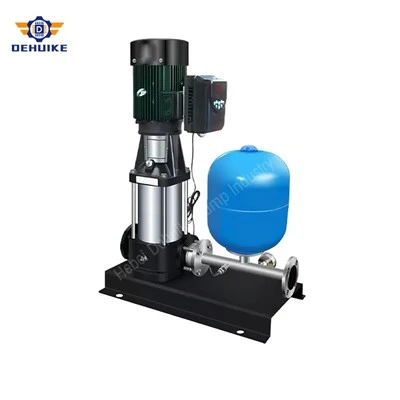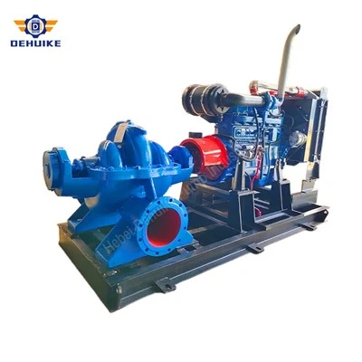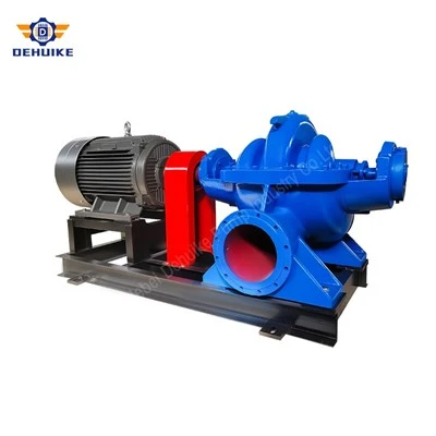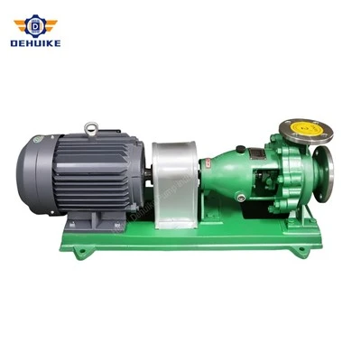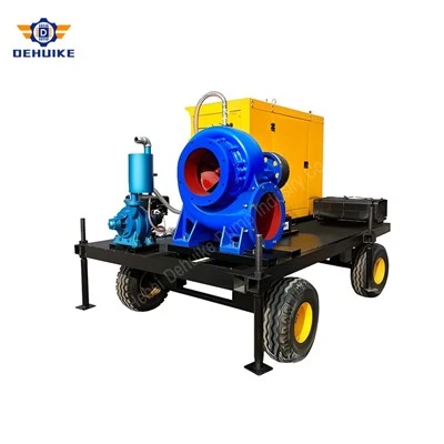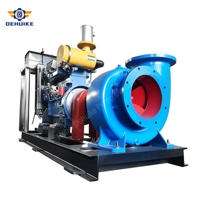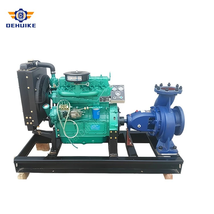
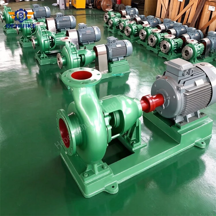
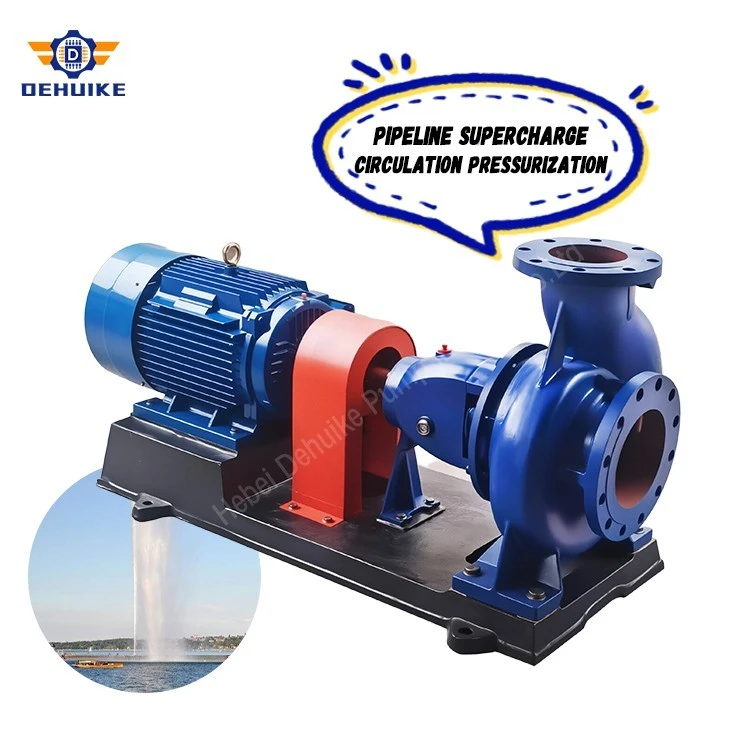
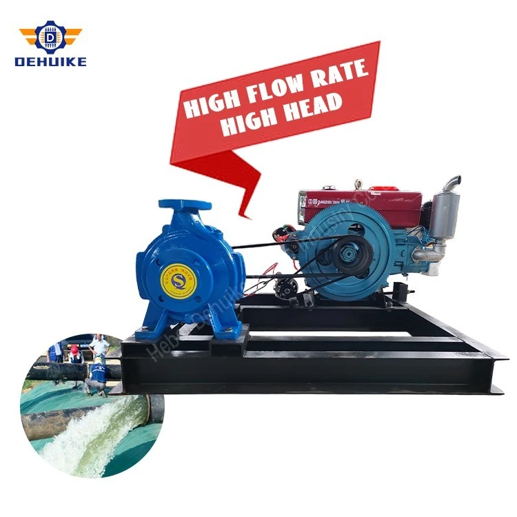
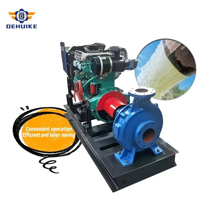
Hebei Dehuike Pump Industry Co., Ltd. is one of the most reliable manufacturers and suppliers of is clear water centrifugal pump in China. With abundant experience, we are committed to providing high quality customized pumps with competitive price. Welcome to wholesale bulk is clear water centrifugal pump for sale here from our factory. Also, pricelist is available.
Introduction: Rotodynamic Principles & Standardization Benchmarks
Operational Thresholds & Media Envelope: The physical media envelope for standard metallurgy comprises potable drinking water, closed HVAC heating and chilling loops, clarified condensate streams, and soft factory utility supplies. Under standard mechanical sealing arrangements, continuous media operating temperatures safely range between -10°C and +80°C. When customized with high-temperature fluoroelastomers, silicon carbide mechanical friction pairs, and an auxiliary cooling water flushing line, the thermal boundary reaches approaching 105 degrees Celsius, accommodating boiler secondary feedwater and low-pressure district heating circulation. Ingested particulate concentration must not exceed 0.1% by total volume, with particle diameters restricted below 0.20 mm to safeguard the tight running clearances of internal bronze wear rings.
Lifecycle Economics & Strategic Procurement: From an engineering procurement and asset management standpoint, adopting an ISO 2858 compliant horizontal pumping platform significantly reduces total ownership expenditure. Standardized flange bolt drillings, center heights, and footprint bolt centers eliminate the need for custom foundation modifications during pump retrofits or facility expansions. Maintenance teams achieve simplified warehouse logistics, interchangeable seal assemblies, and seamless pairing with global electric drivers conforming to IEC and NEMA efficiency standards.
Equipment Characteristics: Hydraulic Equilibrium & Modular Maintenance Architecture
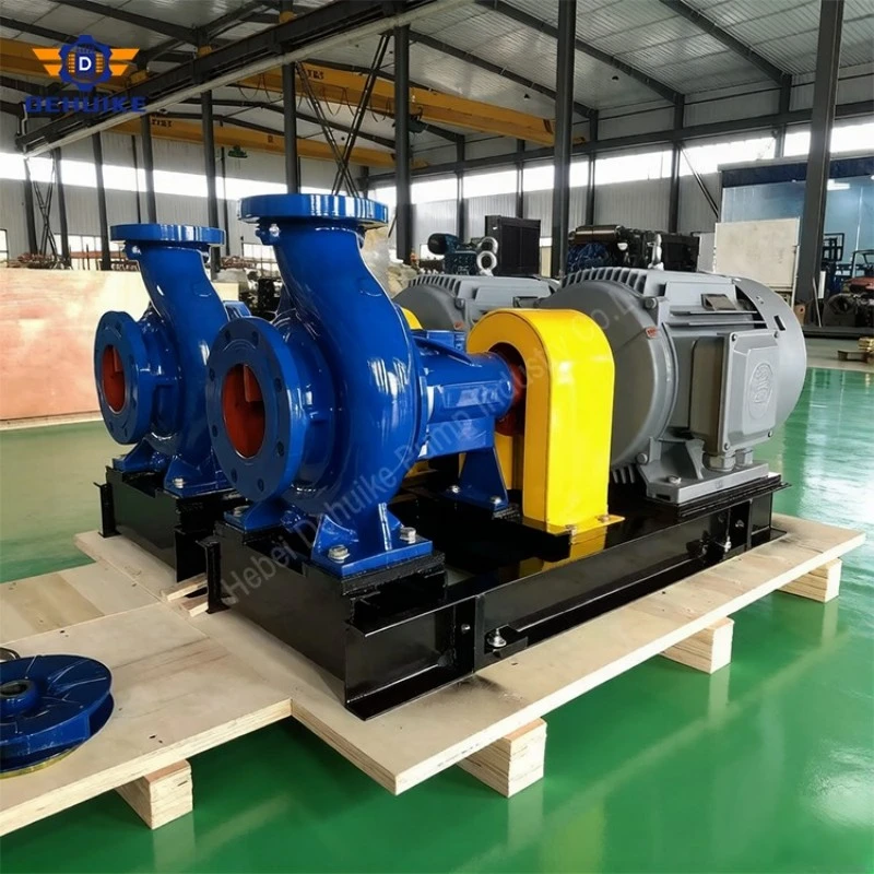
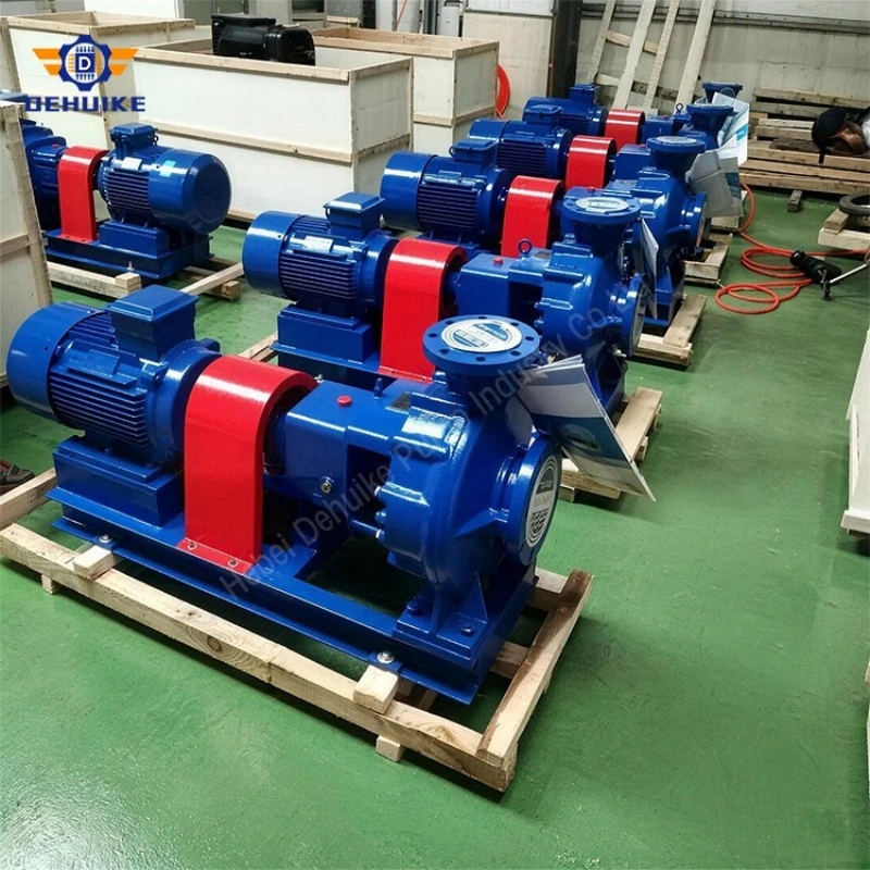
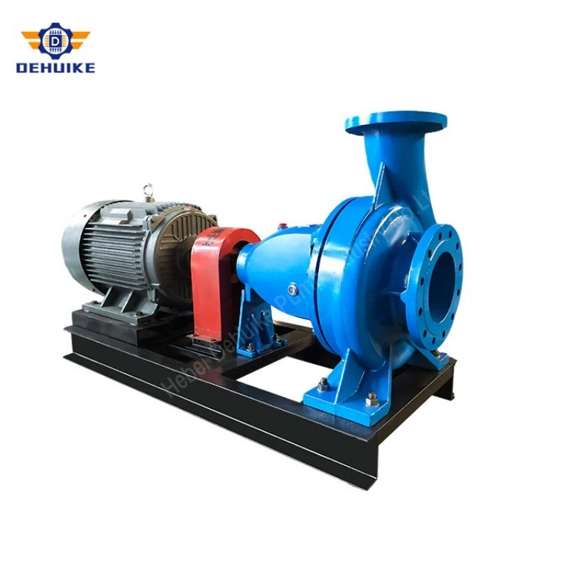
Structural Rigidity & Piping Load Dissipation: A critical engineering objective in continuous plant service is the absorption of mechanical vibration and external fluid piping moments. The pump volute body is cast from high-grade pearlitic grey iron with reinforced wall thicknesses and structural stiffening webs. Heavy integral mounting feet positioned directly beneath the volute spiral bolt securely onto a structural channel-steel foundation skid. This geometry directs external nozzle moments and fluid momentum shocks directly into the reinforced foundation block, protecting internal shafting from bending deflections caused by piping expansion.
Acoustic Attenuation & Low-Vibration Dynamics: Dense pearlitic cast iron provides superior internal material damping compared to welded steel plate fabrication. By dampening rotational harmonics and fluid pressure pulsations, mechanical vibration levels during full-load operation remain strictly within ISO 10816 vibration severity Class A/B criteria, keeping peak velocities under 1.8 mm/s RMS. This vibration stability preserves structural integrity across connected sensor manifolds, pressure gauges, mechanical seal carbon faces, and building structural mounts.
Technical Data & Specifications: Dynamic Performance Ratings Across Selected Frames
Certified Selection Methodology: To provide piping designers, MEP consultants, and plant utility engineers with definitive selection data, the following performance matrices detail certified operating parameters derived from closed-loop hydraulic test dynamometer benches. All data points conform to ISO 9906 precision verification standards. For each pump designation, performance is benchmarked across three standard operating regimes: Minimum Continuous Stable Flow (Q_min), Rated Optimal Efficiency Point (Q_BEP), and overload capacity limit (Q_max).
Hydraulic Affinity Law Optimization: A rigorous understanding of affinity law relationships is essential when adapting pump duty points to actual piping friction profiles. When reducing impeller diameter from full baseline diameter D1 down to trimmed diameter D2, fluid flow Q scales proportionally with (D2/D1), generated discharge head H scales quadratically with (D2/D1)^2, and required shaft brake power P scales cubically with (D2/D1)^3. By utilizing the Trim-A and Trim-B options shown above, engineers avoid the massive parasitic power losses associated with throttling discharge control valves, ensuring electric drivers run consistently inside their optimal load and power-factor window.
Rotational Speed Selection Engineering: Dual-speed operational versatility allows the same physical pump casting to serve vastly different system duties. When energized at 2900 RPM, the unit delivers concentrated discharge pressure for high-rise commercial booster zones and long-distance transmission headers. Conversely, when driven at 1450 RPM, impeller tip speed decreases by half, cutting hydraulic turbulence, reducing acoustic emissions below 68 dBA, and lowering NPSHr down to 2.0 m, making four-pole operation well suited for noise-sensitive institutional installations, hospital cooling plants, and shallow basin extraction.
Production Process: Advanced Casting Metallurgy & Micro-Finish CNC Machining
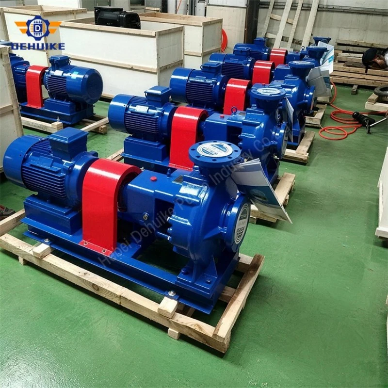
Precision Foundry Molding & Thermal Stress Relieving: The exceptional field longevity of the IS Clear Water Centrifugal Pump is established directly on the foundry floor. Volute casings, suction covers, and bearing pedestals are produced utilizing advanced resin-bonded sand mold casting technology. Raw scrap steel and pig iron melts undergo computerized spectral analysis prior to pouring, ensuring chemical compositions adhere strictly to HT200/HT250 metallurgical specifications (carbon 3.0-3.3%, silicon 1.6-1.9%, manganese 0.7-0.9%). Pouring temperatures are digitally monitored at 1380°C to 1420°C to guarantee dense pearlitic graphite flake distribution, completely eliminating macro-porosity, cold shuts, and sand inclusion defects. After cooling, all structural castings undergo a stress-relief thermal annealing cycle at 550°C, relieving internal cooling stresses to ensure dimensional stability during subsequent precision machining.
Multi-Axis CNC Machining & Geometric Tolerancing: Rough castings proceed to high-precision horizontal CNC machining centers, where critical dimensional surfaces are machined in single-clamping operations. Flange sealing faces, internal casing wear ring registers, and rear backplate spigots are turned and milled under unified reference datums, ensuring absolute geometric concentricity and perpendicularity within 0.02 mm. This extreme machining accuracy prevents eccentric wear on rotating wear rings and eliminates radial binding on mechanical seal stationary seats.
40Cr Alloy Rotor Shaft Forging & Cylindrical Grinding: Drive shafts are hot-forged from structural alloy steel grade 40Cr. Forgings undergo thermal oil quenching and tempering within a metallurgical hardness window of 240–280 Brinell (HBW), imparting high fatigue resistance against alternating torsional and bending moments. Critical bearing journals, shaft sleeve contact lands, and coupling taper fits are finished on high-precision cylindrical grinding machines to a surface finish of Ra 0.4 µm, ensuring minimal frictional drag and intimate contact with bearing inner rings.
Dynamic Rotor Balancing to ISO 1940-1 Grade G2.5: Every cast bronze or ductile iron impeller undergoes two-plane dynamic balancing on computerized dynamic balancing rigs in accordance with ISO 1940-1 Grade G2.5 standards. Correction is accomplished via precision CNC milling on the outer crown of the impeller shrouds, strictly avoiding the attachment of external balancing weights that could detach under fluid turbulence. Dynamically balanced rotors eliminate centrifugal unbalance forces, ensuring vibration-free rotation and safeguarding deep-groove ball bearings from cyclic impact fatigue.
Cleanroom Mechanical Assembly & Runout Verification: Pump assembly takes place within dedicated dust-controlled assembly bays following a standardized sequence of quality checkpoints. Technicians utilize induction heaters to expand bearing inner rings during shaft fitment, avoiding destructive mechanical impact. After mounting the rotating element inside the bearing housing, multi-point dial indicator gauges measure total radial shaft runout at the seal sleeve position, verifying that dynamic runout remains strictly within 0.025–0.030 mm. Internal axial float is precisely calibrated using ground shim packs before final bolt torqueing with calibrated digital torque wrenches.
Quality Assurance: Hydrostatic Pressure Qualification & Dynamometer Test Certification
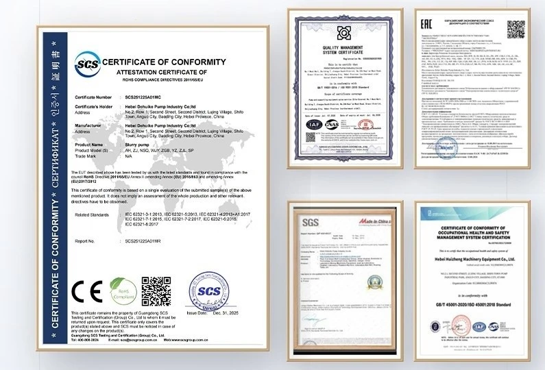
100% Hydrostatic Pressure Proof Verification: Quality assurance procedures at Dehuike are audited under ISO 9001:2015 quality frameworks, enforcing comprehensive factory qualification before crating. Every raw unmachined volute casting is sealed, filled with treated water, and subjected to casing pressure proofing at 24 bar (2.4 MPa, exceeding nominal ratings by 150%). Pressure is maintained sustained over a continuous 15-minute hydrostatic hold while acoustic sensors and pressure loggers confirm absolute zero casing weeping, micro-cracking, or pressure decay.
Automated Hydraulic Dynamometer Testing: Finished pumps are mounted on our fully automated recirculating test loop. Calibrated according to Grade 2B testing specifications per ISO 9906, the test bench features electromagnetic induction flowmeters, calibrated digital pressure transmitters, dynamic torque sensors and digital optical speed pickups. Each machine is tested across multiple calibrated flow resistance points-from shut-off head to maximum runout flow-generating certified real-time head-capacity (H-Q), shaft power (P-Q), and hydraulic efficiency (η-Q) curves that confirm guaranteed contractual performance.
Triaxial Dynamic Vibration & Bearing Thermal Logging: During the full-speed performance verification run, triaxial piezoelectric accelerometers are magnetically mounted on the bearing pedestal to measure tri-directional orthogonal planes (X, Y, and Z axes). Recorded vibration velocities must strictly remain below 1.8 mm/s RMS under ISO 10816-3 evaluation metrics. Concurrently, non-contact infrared pyrometers monitor bearing oil bath temperatures throughout a continuous thermal stabilization run, confirming bearing temperature rise does not exceed 35°C above ambient temperature (with total operating temperature capped below 70°C).
EN 10204 Type 3.1 Certification & Export Dossier: Every exported consignment includes a comprehensive Quality Dossier containing: (1) Factory Shell Pressure Proof Record, (2) ISO 9906 Dynamometer Test Log & Hydraulic Performance Curves, (3) EN 10204 Inspection Certificate Type 3.1 detailing chemical melt analytics, (4) Dynamic Impeller Rotor Balancing Sheet, and (5) Formal Declaration of CE, EAC, and RoHS Conformity.
Application Scope: Urban Booster Networks, Industrial Chilling & Agricultural Irrigation
Municipal Potable Water Booster Pumping Stations: In municipal drinking water utility networks and regional water treatment works, the IS Clear Water Centrifugal Pump acts as the continuous prime mover for distribution boosting. Operating in parallel configurations across regional pumping stations, these pumps lift clarified potable water from underground clear-water reservoirs into elevated storage towers or directly into urban municipal water mains. The smooth hydraulic passages and non-pulsating centrifugal discharge protect aging municipal distribution mains from cyclic pressure fatigue, delivering dependable, steady line pressures across peak morning and evening domestic demand periods.
Industrial Plant Utility & Secondary Cooling Circulation: Continuous industrial manufacturing requires vast volumes of clean cooling water to stabilize critical thermal processes. In chemical manufacturing complexes, steel rolling mills, and automobile assembly plants, IS pump skids drive closed-circuit secondary cooling circuits, circulating chilled recirculating water through cooling tower heat exchangers, blast furnace cooling jackets, and welding robot manifolds. The grey iron body paired with a sacrificial protective sleeve machined from martensitic 2Cr13 stainless alloy provides superior resistance against dissolved atmospheric carbonates and mild scale inhibitors, ensuring uninterrupted production cycles.
Commercial District HVAC & High-Rise Hydronic Loops: Modern high-rise commercial complexes, corporate data centers, and airport passenger terminals rely on central chiller plants for thermal climate management. IS horizontal end-suction pumps serve as the primary condenser water and chilled water circulation engines within these large-scale HVAC hydronic systems. When coupled to 1450 RPM low-speed 4-pole electric motors, the pumps deliver massive volumetric circulation while keeping mechanical acoustic noise within comfortable plant room acoustic thresholds, eliminating low-frequency hum transmission into occupied building spaces.
Agricultural Pressurized Fertigation & Pivot Booster Pumping: Agricultural irrigation schemes require pumps that combine high volumetric efficiency with exceptional mechanical durability under outdoor environmental conditions. The IS series is widely deployed across modern pressurized drip irrigation manifolds, center-pivot irrigation booster stations, and river canal water lifting installations. Capable of direct electric motor coupling or diesel engine belt/direct drive integration, the pump provides steady discharge pressure to overcome friction losses in long-distance buried PVC pipe networks, ensuring uniform water and nutrient distribution across expansive crop acreage.
Manufacturing Scale, Quality Commitments & International Export Services
Over 30 Years of Specialized Manufacturing Heritage: With over 30 years of dedicated manufacturing experience in the fluid machinery industry, DHK Pump (operated by Hebei Dehuike) stands as an authoritative international manufacturer of industrial centrifugal machines, abrasive slurry pumps, and engineered fluid packages. Our engineering heritage combines classical rotodynamic hydrodynamics with advanced automated manufacturing processes, allowing us to supply standardized and custom-engineered pumping solutions to engineering, procurement, and construction (EPC) contractors and fluid machinery distributors worldwide.
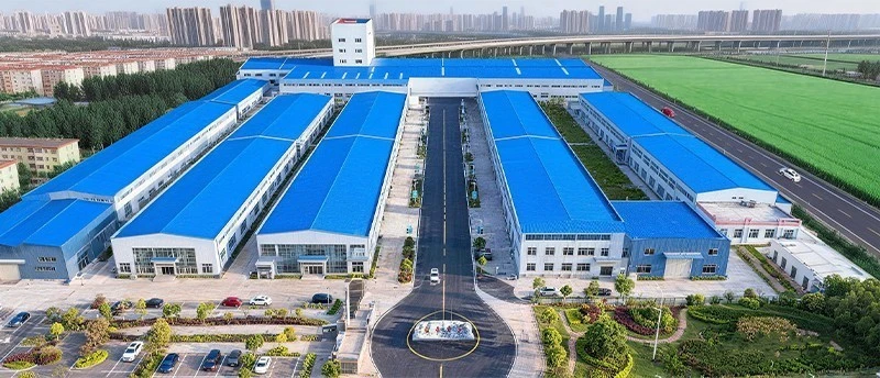
6,000+ m² Production Complex & 900+ Certified Component Partners: Our state-of-the-art manufacturing campus spanning 6,000+ m² integrates modern casting lines, heavy-duty CNC machining bays, automated impeller dynamic balancing cells, and computerized closed-loop hydraulic dynamometer testing stations. Supported by an integrated manufacturing ecosystem comprising 900+ vetted supply partners-specializing in premium silicon carbide mechanical seals, high-grade 40Cr alloy forgings, and international efficiency motors-we maintain lean manufacturing cycles capable of shipping standardized bare-shaft pumps and packaged skids within a rapid window of 10–15 working days.
Comprehensive 24-Month Equipment Warranty & EPC Technical Support: Demonstrating our complete confidence in mechanical integrity and manufacturing craftsmanship, Dehuike provides an extensive two-year manufacturer guarantee (24 full months) safeguarding the entire rotodynamic assembly, with the natural exclusion of consumable friction components. Our international engineering desk provides full lifecycle technical consultation, including piping friction calculations, system NPSHa analysis, 3D STEP CAD plant layout integration, and customized motor windings engineered to interface with global electrical grids spanning 200V through 690V at both 50 Hz and 60 Hz line frequencies, integrating high-efficiency induction motors (IE3/IE4 ratings) with explosion-proof and high-protection enclosures (IP55 to IP66).
FAQ: Technical Sizing, Piping Optimization & Field Commissioning Procedures
Q1: How should plant design engineers evaluate the operational trade-offs between two-pole (2900 RPM) and four-pole (1450 RPM) rotational speeds when specifying an IS Clear Water Centrifugal Pump?
The selection between 2-pole (2900 RPM) and 4-pole (1450 RPM) speeds depends primarily on system head requirements, available suction pressure, and noise limitations. Operating at 2900 RPM provides high head generation in a compact pump casing, making it economical for high-pressure booster systems. However, 2900 RPM operation incurs higher liquid velocities, higher NPSHr values (typically 2.5 m to 5.0 m), and higher sound pressure levels. Operating at 1450 RPM reduces impeller peripheral tip speed by half, which cuts hydraulic turbulence, lowers NPSHr down to 2.0 m, slashes acoustic noise below 68 dBA, and significantly reduces mechanical wear on bearings and mechanical seal faces. For continuous plant services requiring low noise and long MTBM, 1450 RPM is strongly recommended.
Q2: What calculation methodology must piping consultants follow to confirm adequate available suction head (NPSHa) and prevent acoustic cavitation erosion?
Cavitation occurs when static pressure in the pump suction eye drops below the vapor pressure of the pumped fluid, forming vapor bubbles that collapse violently against the impeller vanes. NPSHa must be calculated using the physical equation: NPSHa = (P_atm / (ρ*g)) + H_static - H_friction - (P_vap / (ρ*g)), where P_atm is atmospheric pressure, H_static is the liquid level elevation relative to the pump shaft centerline, H_friction is total friction head loss across suction valves, strainers, and piping, and P_vap is fluid saturation pressure at ambient or elevated operating temperatures. For reliable long-term service, suction margin NPSHa relative to catalog NPSHr must exceed a minimum threshold of 0.8 to 1.0 m across all suction liquid levels.
Q3: Why do engineering piping standards forbid concentric reducers on horizontal pump suction nozzles, mandating flat-on-top eccentric geometries instead?
When transitioning from a larger horizontal suction pipe to the pump inlet nozzle, an eccentric reducer with a flat-top orientation must always be used. A concentric reducer creates a high-point pocket along the top of the pipe where entrained air or vapor bubbles accumulate. Under high fluid velocities, this air pocket is pulled into the impeller eye in bulk slugs, causing instantaneous loss of hydraulic prime, severe pressure pulsations, shaft vibration, and dry-running damage to mechanical seal faces. Installing an eccentric reducer flat-on-top maintains a continuous downward or horizontal flow vector, ensuring air travels through without pocketing.
Q4: In what fluid environments should operators transition from traditional braided compression packing to a single mechanical face seal with Plan 11 recirculation?
Gland packing relies on a braided PTFE/synthetic yarn packing ring compressed inside the stuffing box, requiring a continuous controlled leak rate of 10 to 20 drops per minute to lubricate and cool the shaft sleeve. This causes minor fluid loss and requires periodic mechanical gland tightening. Conversely, a mechanical seal provides completely leak-free operation, eliminating housekeeping cleanups and preventing moisture damage to adjacent bearings. API piping arrangement Plan 11 circulates a clean bypass stream from the pump discharge nozzle through an engineered orifice plate directly across the mechanical seal friction faces, dissipating frictional heat and preventing vapor bubble entrapment in the seal chamber.
Q5: Why does extended low-flow operation below the minimum stable threshold trigger severe thermal buildup, and how should bypass piping be sized?
Operating a centrifugal pump at severely throttled flows below its continuous minimum hydraulic threshold (MCSF, generally bounded within 25% to 30% of Rated Optimal Efficiency Point flow) causes severe internal recirculation vortices at the impeller inlet and cutwater tip. This fluid recirculation generates destructive radial deflection on rotor bearings alongside rapid heating as mechanical shaft power is converted directly into thermal energy. To safeguard pumps in automated facilities where downstream process valves may shut completely, an automatic recirculation protection valve (ARV) or a permanent minimum-flow bypass conduit returning to the suction source tank must be installed.
Q6: What sequence of valve positioning and electrical motor starting is necessary to commission an end-suction pump without inducing severe pipeline water hammer?
Starting a centrifugal pump against an empty discharge line with an open discharge valve causes extreme runout flow, resulting in severe motor over-amperage and destructive fluid water hammer when the liquid column suddenly impacts air vents or closed terminal valves. The correct commissioning protocol requires closing the discharge gate/butterfly valve completely, verifying suction flooding and casing air venting, starting the motor, and slowly opening the discharge valve over a period of 15 to 30 seconds once discharge pressure stabilizes. In modern VFD-driven systems, a controlled acceleration ramp profile can be programmed into the motor drive to pressurize the pipeline progressively.

Hot Tags: is clear water centrifugal pump, China is clear water centrifugal pump manufacturers, suppliers, factory