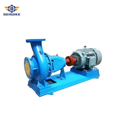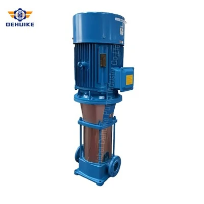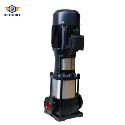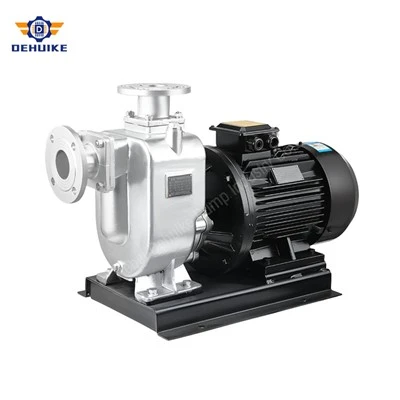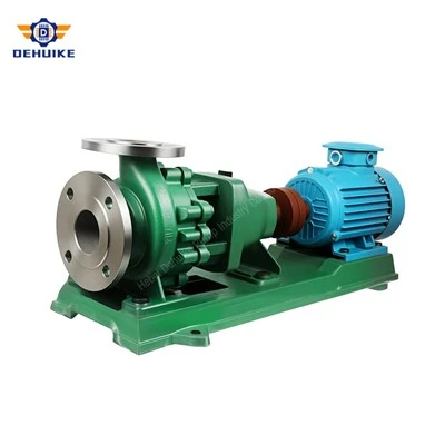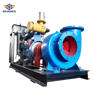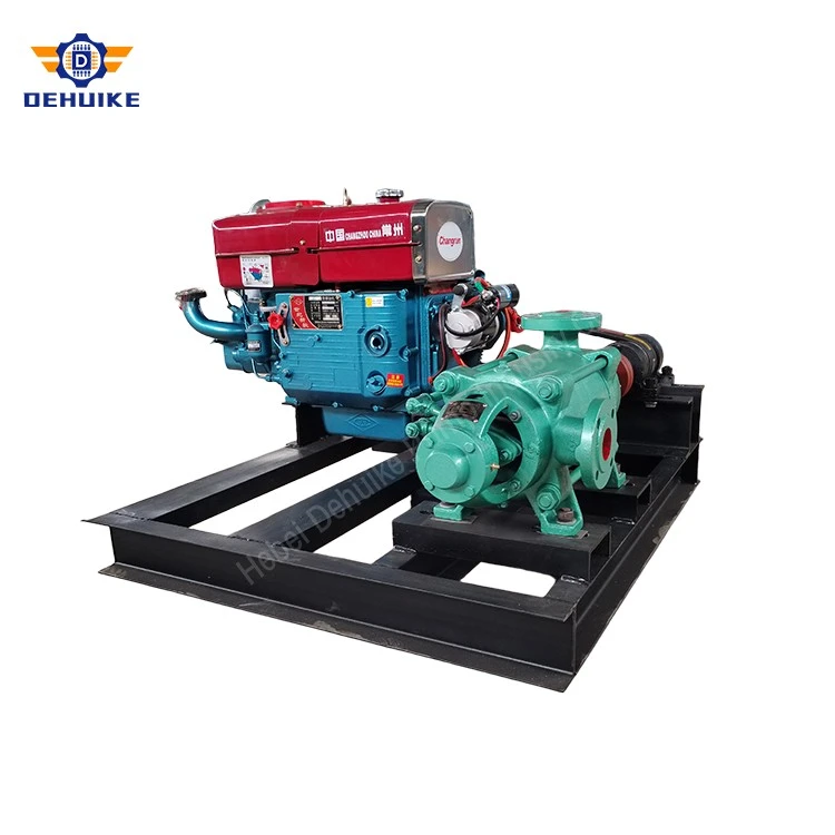
Hebei Dehuike Pump Industry Co., Ltd. is one of the most reliable manufacturers and suppliers of high head multistage pump in China. With abundant experience, we are committed to providing high quality customized pumps with competitive price. Welcome to wholesale bulk high head multistage pump for sale here from our factory. Also, pricelist is available.
Introduction
Most of the engineering attention on a multistage pump goes into selection: flow, head, stage count, efficiency, NPSH. Then it arrives on a lorry, is bolted to a plinth steel, and connected to pipework by whoever is on site that week. A large share of the failures in the first year are introduced in those two days, and they do not look like installation faults afterwards - they look like a balance disc wearing early, a joint seeping at the discharge head, a bearing running hot, or a pump that has never been quiet.
The reason a multistage machine is more sensitive than a single-stage one is structural. It is not a monolithic casting. It is a stack of stage casings, clamped end to end by tie rods around one long shaft, mounted on bearing pedestals at both ends. Anything that bends that stack - pipe flanges that do not line up, a baseplate that is not flat, a coupling pulled to a convenient gap - is bending the pressure boundary and loading the bearings at the same time.
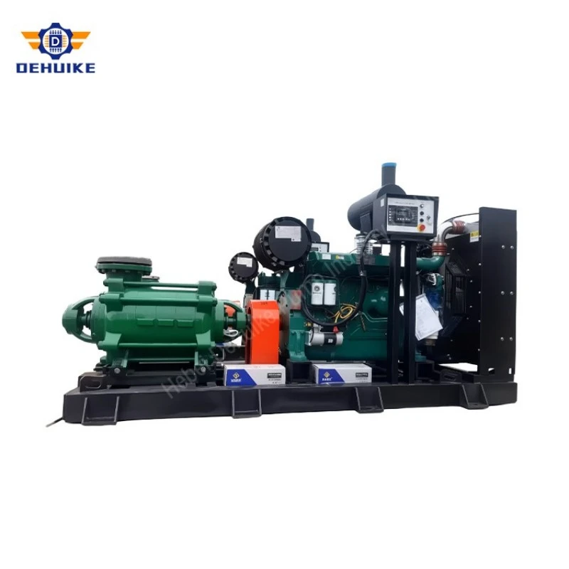
The stack is not a rigid body
On a ten-stage machine carrying 500 m, the casing between the last stage and the discharge head contains the full 5 MPa. That joint is held closed by tie rods, and the tie rods hold the whole stack in compression. If the discharge pipe is short, misaligned or restrained by a hot pipe run, the flange pull acts on that joint through a lever arm as long as the stack. The consequence is not usually a visible crack. It is a joint that seeps, a stage register that opens a fraction, and a rotor that is no longer concentric with the diffusers.
The rule on site is that pipe flanges are brought to the pump, never the pump to the flanges. Bolt holes are aligned with the casing free and the baseplate grouted, and any gap at a flange is made up with a spool piece or a machined spacer, not with bolt tension. Flexible couplings and expansion joints reduce transmitted load, but they do not correct a pipe that has been pulled into position.
Nozzle load limits exist for this reason, and they are small compared with what a fabricator will accept without complaint. If the suction and discharge mains cannot be brought into line within the published limits, the pump needs a properly supported spool and a pipe anchor nearby, not a heavier flange.
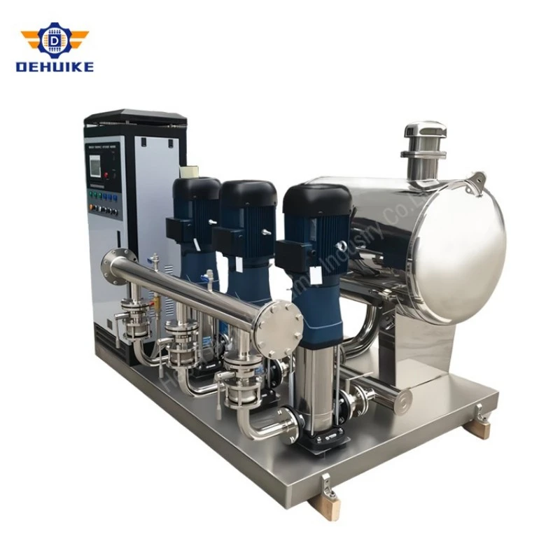
Foundation, baseplate and grout
A horizontal multistage pump is long, heavy at the discharge end because of the motor, and sensitive to any settlement that changes the shaft line. The foundation therefore has to do two things: carry the mass with the motor, and stay flat. Mass matters because a light plinth on a flexible slab will vibrate with the machine; a foundation with several times the pump-and-motor mass absorbs that energy instead of returning it.
The sequence is where most installations go wrong. The baseplate is set on shims or jacking screws, levelled in both directions, and checked for squareness to the pipe runs before any grout is placed. Grout goes in as one continuous pour with the baseplate anchored, so that the plate is supported over its whole area rather than at four points. A baseplate grouted in two stages, or grouted before being levelled, will have a permanent bow that no amount of shimming afterwards can remove - and a bowed plate loads the pump feet unevenly, which is visible later as a soft foot at one corner and a bearing that runs hotter than the other.
Anchor bolts are tightened in a cross pattern after the grout has reached its specified strength, not during the pour. The pump feet are then checked for contact with a feeler gauge at each bolt, and any gap is shimmed rather than closed by tightening: a foot that is pulled down by its bolt twists the casing, and a twisted casing is a misaligned bearing housing.
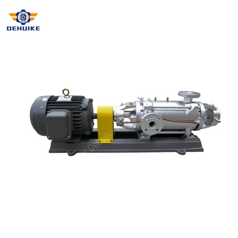
Alignment: cold is only half the number
Cold alignment is done with the pump at ambient temperature and the motor uncoupled, using dial gauges or a laser on the coupling halves, reading both parallel and angular offset at four positions through a full rotation. The target is not "as close as possible"; it is the figure in the manufacturer's alignment sheet, which is already offset to allow for the thermal growth that will occur when the machine reaches operating temperature.
That is why a pump aligned to zero at ambient can be out of tolerance when hot. A boiler feed machine moves at the discharge end as the casing and the water in it warm up, and the motor moves less; the cold setting anticipates the difference. Setting both to zero looks like good work and produces a machine that runs misaligned for its whole life. The general practice is to align cold to the specified offset, run the pump to temperature, and then re-check and record the hot reading before accepting the installation.
Soft foot deserves its own check. With the coupling disconnected and the pump feet bolted, a dial gauge on the foot reads any lift as each bolt is loosened in turn. A foot that lifts more than a few hundredths of a millimetre will distort the casing every time the bolt is tightened, and the alignment done afterwards will not hold. Correcting it means shimming the foot, not over-tightening the others.
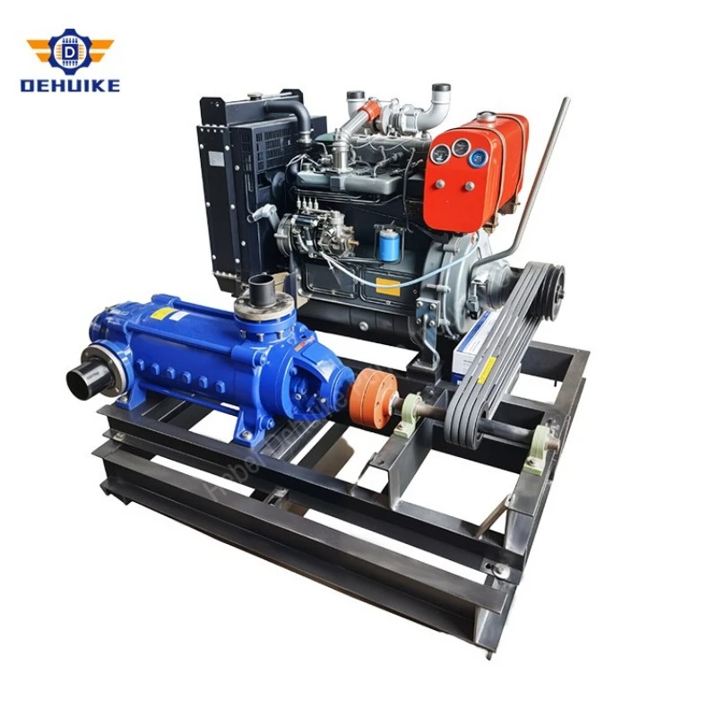
The coupling gap is not a free variable
Between the two coupling halves there is a gap, and on a multistage pump that gap interacts with the rotor's axial float. The rotor is positioned by the thrust bearing and, on larger machines, by a balance disc that carries the residual axial force. Both need a defined range of axial movement to work; a rotor held against its thrust face by the coupling has no float left to give.
So the gap is set to the manufacturer's figure with the rotor in its correct axial position, and the axial float is measured before and after the coupling is closed. An installer who finds the gap too wide and pulls the motor forward to close it may have preloaded the thrust bearing by a few hundredths of a millimetre - enough to run hot immediately, and enough to wear the balance disc long before its time. The same mistake in the other direction leaves the coupling loose and produces axial vibration and a knocking noise at start.
Flexible couplings do not correct radial misalignment. They absorb a small angular and axial movement, and they transmit the rest as load to the bearings. A coupling that looks fine because it turns freely by hand proves nothing about alignment; the gauges do.
Table 1 Installation checks and what each one protects
|
Check |
Measured how |
What it protects |
|
Baseplate level and grout contact |
Level and feeler gauge before grout |
Even foot loading; no casing twist |
|
Soft foot |
Dial gauge on each foot as bolts are loosened |
Casing distortion at every reassembly |
|
Cold alignment offset |
Dial gauge or laser, four positions |
Bearing load at operating temperature |
|
Coupling gap against axial float |
Feeler gauge plus axial dial reading |
Thrust bearing and balance disc life |
|
Hot alignment |
Re-read after reaching operating temperature |
Confirms the cold offset was correct |
|
Tie rod torque |
Calibrated wrench, cross pattern |
Joint sealing at full discharge pressure |
|
Pipe flange bolt freedom |
Bolts turn by hand before tightening |
No pipe strain into the stage stack |
First start: fill the stack, not just the suction

A multistage pump has to be filled stage by stage, and the filling is only complete when water appears at the vent at the top of the discharge head. Filling until the suction gauge reads pressure is not enough: the first stage can be full while the upper stages hold air, and the machine will then run with a mixture for the first minutes, with the discharge pressure hunting and the seals running dry at the top of the stack.
The sequence that works is unhurried: confirm rotation by hand or by a brief jog with the coupling exposed, open the suction valve fully, open the vent, fill until water is continuous at the vent, close it, start with the discharge valve open and bring the machine up to flow before throttling to the duty point. Running against a closed discharge, even for the seconds it takes to open a valve, is the fastest way to heat a small volume of water inside a high-head casing.
Then record the baseline, because everything later is measured against it: vibration velocity at each bearing housing in three directions, bearing temperatures, seal leakage rate, motor current at the duty point, and the discharge pressure. These five readings taken on the first day are what make a rising trend visible six months later; without them, every subsequent complaint starts from opinion.
The first hundred hours
Thermal stabilisation changes the geometry of a new installation, so the checks that matter come after the machine has been at temperature, not before. Re-read the alignment hot. Re-check the coupling gap with the rotor float unchanged. Re-torque the tie rods to the specified figure in a cross pattern after the first few heat cycles, since the stack settles as the gaskets and registers take their final compression. Look at the joint between the last stage and the discharge head for any seepage - a dry joint after a week of running at full pressure is the best evidence that the stack was assembled and loaded correctly.
If the machine has a mechanical seal with a flush or quench connection, verify the flow at the seal after the first week rather than at commissioning. A throttled flush valve is a common short-cut, and the seal fails months later for a reason nobody connects to the installation.
What each symptom points back to
Installation faults declare themselves in a small number of recognisable ways, and each one points to a specific item on the list above.
Seepage at the discharge-head joint. Pipe strain into the stack, or tie rods torqued unevenly. Re-check flange freedom before blaming the gasket.
Hot bearing at one end only. Soft foot or a baseplate bow on that side, or cold alignment set to zero instead of the specified offset.
Axial vibration and knocking at start. Coupling gap wrong for the rotor float, or a balance disc that has already worn because the rotor was preloaded.
Noise and pressure hunting in the first minutes. Air left in the upper stages; the vent at the discharge head was not used or the fill was too fast.
Gradual loss of head over the first year. Wear ring clearance opening faster than expected, often because the rotor is not concentric - a consequence of casing distortion from pipe load or soft foot.
Hot Tags: high head multistage pump, China high head multistage pump manufacturers, suppliers, factory