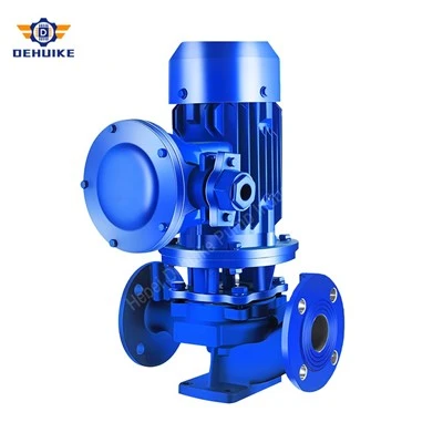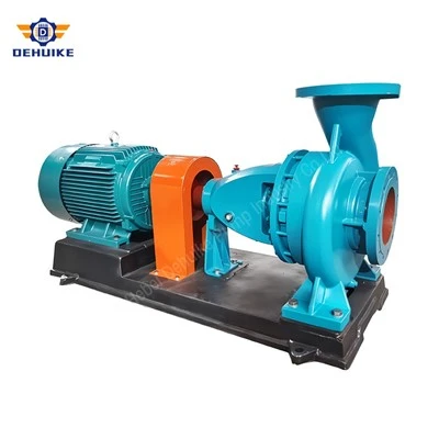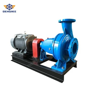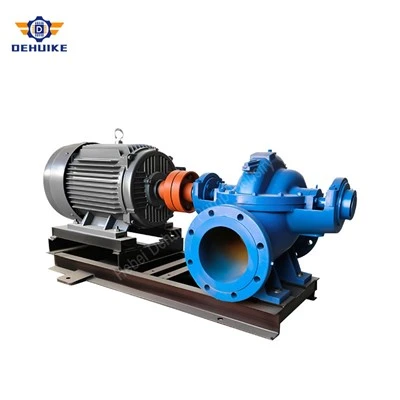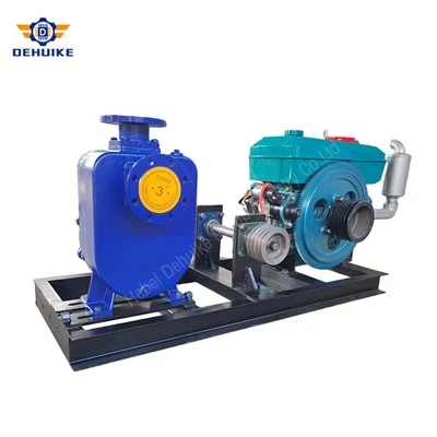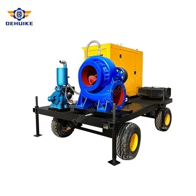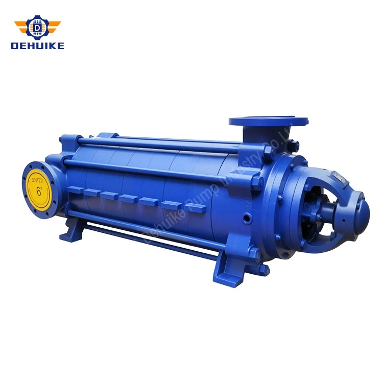
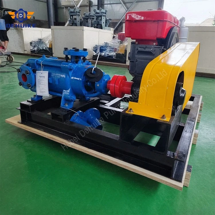
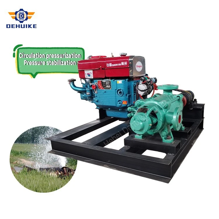
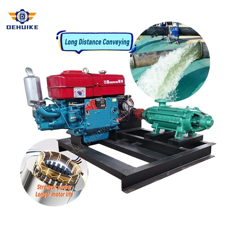
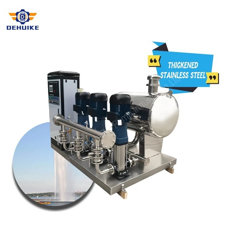
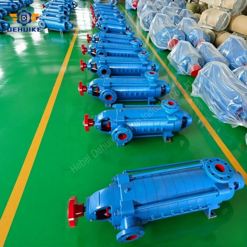
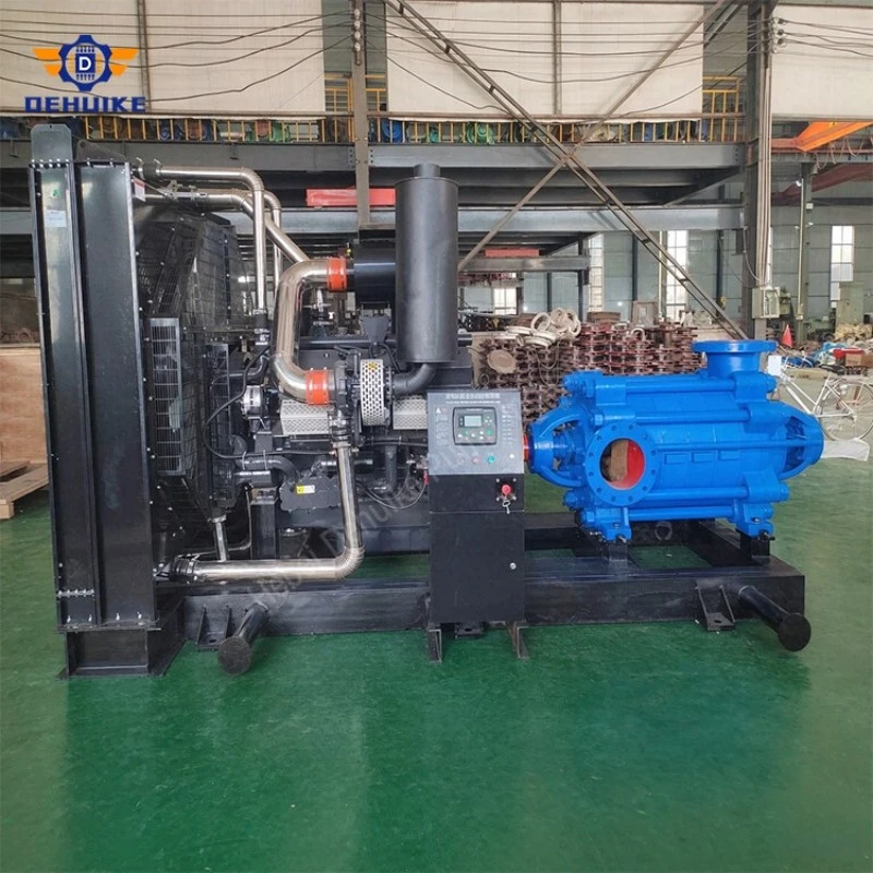
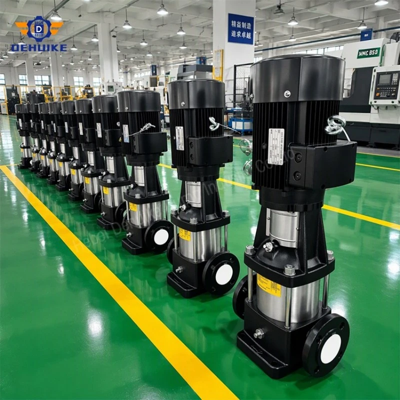
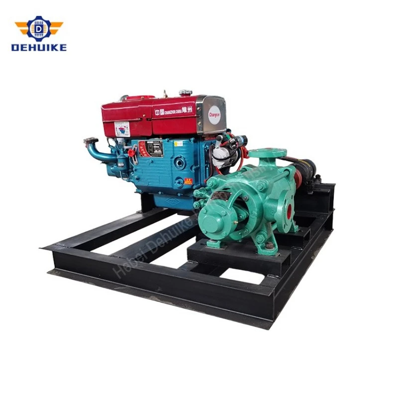
Hebei Dehuike Pump Industry Co., Ltd. is one of the most reliable manufacturers and suppliers of horizontal multistage centrifugal pump in China. With abundant experience, we are committed to providing high quality customized pumps with competitive price. Welcome to wholesale bulk horizontal multistage centrifugal pump for sale here from our factory. Also, pricelist is available.
The Flow Comes From the Calculation
Fire flow is usually written in litres per minute, the unit sprinkler density arrives in. Pump data sheets prefer litres per second, or cubic metres per hour. Reconcile the two before any other step.
Take a design area of 180 m² covered at 6.1 L/min per m². That is 1,098 L/min, or 18.3 L/s. Add two hydrant outlets at 6.3 L/s each and the total reaches 30.9 L/s. A rack protection demand of 24 L/s takes it to 55. So the duty is not a guess; it is areas, densities and outlets added up, and it should arrive with the sheet that produced it.
Two conversions do most of the work in this trade. Multiply litres per second by 3.6 to get cubic metres per hour, so 55 L/s becomes 198 m³/h. Divide head in metres by 102 to get megapascals, so 97 m sits just under 0.95 MPa. Get those wrong and a 30% error can pass unnoticed through a whole quotation.
Build the Head from Components
Head is not a single figure pulled from a table. It is four or five items added together, and each has a source.
For this building the parts add up as follows: 42 m of static lift to the top sprinkler; 36 m of residual wanted there, near 0.35 MPa, enough to feed a hose line; 8 m lost in riser and branches; 6 m across the backflow device on the town main; 1.5 m through strainer and fittings. That totals 93.5 m, and a 4 m construction allowance brings the duty to 97 m.
Friction deserves its own check rather than a rule of thumb. For 198 m³/h through 30 m of DN200 pipe with a C factor of 120, the Hazen-Williams relation gives roughly 0.5 m of loss. The same flow through DN150 over the same length gives about 1.9 m. Bore size, more than run length, is what moves that figure.
Table 1 Friction loss over 30 m at 198 m³/h, C = 120
|
Bore |
Internal diameter (mm) |
Velocity (m/s) |
Loss (m) |
|
DN150 |
152 |
3.03 |
1.9 |
|
DN200 |
203 |
1.70 |
0.5 |
Where a backflow preventer is required, ask for its loss at the design flow. A device quoted at 6 m when passing 30 L/s may take 15 m when passing 55. It is the item most often omitted from the sum, and the usual explanation for a unit that turns out "short" once the building is running.
What the Double Suction Cancels
Water enters the impeller at both sides. Each eye sees half the flow, and the pressure acting on the two sides pushes in opposite directions along the shaft.
That matters for bearing life. Take an impeller eye of 200 mm outer diameter with a 60 mm shaft hub. The annulus area is 0.0286 m². At 0.95 MPa the unbalanced force works out near 27 kN, roughly the weight of a small car, all of it pushing the shaft toward the driver. A single-eye impeller of the same size would put that load into one bearing set. Two eyes cancel most of it, which is why this layout suits long unattended runs and why the bearings in a split case machine usually outlive the seals.
The same geometry explains the maintenance story. Both flanges sit on the lower half of the casing. Lift the top half and the shaft, impeller and bearing housing come out together. Wear rings, mechanical seals and bearings can be changed with the fire main still full, provided the isolation valves are fitted and closed. Buildings that cannot be drained during working hours get real value from that.
The Three Points an Acceptance Test Will Check
A fire unit does not live at its rated point. It sits still for weeks, starts on a pressure drop, and gets measured at flows well beyond the number on the nameplate. Any curve offered for this duty should be readable at three places.
Shutoff comes first. With a rating of 97 m, the 140% ceiling used in NFPA 20 practice allows 136 m at closed valve, or 1.33 MPa bearing on pipe, valves and anything downstream. Pipe class and relief setting are judged at that figure, not at the rating.
Relief sizing needs its own number. A valve set near 1.4 MPa, under the pipe class but above the highest head the intake can add, and passing about a quarter of rated flow, roughly 14 L/s here, gives excess water a route out before casing pressure becomes the issue.
The second point is the rating itself: 55 L/s at 97 m. The third is the overload point, 150% of rated flow, where the unit must still hold at least 65% of rated head. Here that means 82.5 L/s at 63 m. A curve that droops below 63 m at that flow fails, even if its efficiency looks healthy.
Put the arithmetic in one place and the picture becomes clear.
Table 2 Computed duty for the worked example
|
Flow (L/s) |
Head (m) |
Efficiency |
Shaft power (kW) |
Reading |
|
55 |
97 |
0.72 |
72.7 |
Rating; motor selected above this |
|
82.5 |
63 |
0.68 |
75.0 |
150% flow; 65% head still held |
Shaft power comes from the hydraulic relation: density times gravity times flow times head, divided by efficiency. At the rating, 1000 x 9.81 x 0.055 x 97 / 0.72 gives 72.7 kW. At the overload point the flow rises by half while the head falls by a third, and the result is 75.0 kW. The open end of the curve draws more power than the rating, which is the whole reason a 75 kW motor is specified instead of a 72.7 kW one.
Suction, Where Arithmetic Is Less Forgiving
Suction problems are not cured by bigger pumps. They are prevented by adding up the available margin before the unit is ordered.
Available NPSH is atmospheric pressure minus vapour pressure, plus or minus the static level, minus friction in the intake line. A tank with its surface 2.5 m above the pump, water at 80 °C and 0.7 m of intake loss gives: 10.2 m for atmosphere, plus 2.5 m for the level, minus 4.8 m for vapour pressure at that temperature, minus 0.7 m for friction. The result is 7.2 m.
Required NPSH for this duty is about 5.4 m at the overload flow. The margin is 1.8 m, which is workable but not generous. Check it at the highest flow and the lowest tank level the design permits, because that is the combination a real building produces on a bad day.
One more arithmetic item: intake velocity. At 55 L/s through DN200 with an internal diameter near 203 mm, velocity is about 1.7 m/s. Through DN150 it reaches 3.0 m/s, which is enough to pull air down a vortex and to make a short radius bend noisy. A DN200 intake costs more pipe and less trouble.
Set Points, Delay and the Weekly Run
Three pressures decide how the package behaves, and they need separation, not decoration.
The holding pump cuts in first, at the pressure where normal leakage has lowered the line. It cuts out above that. The main unit starts lower still, and once started it keeps running until someone stops it. A controller that stops itself when pressure recovers will shut down a pump while a fire is still burning, so the stop is manual by design. Explain that at handover; operators trained on booster sets expect the opposite.
Overlapping settings are the usual fault. A holding pump that cuts in below the main start point will wake the big machine for every small leak; one that cuts out above it will fight the main unit. Put the three figures on a label inside the panel, then prove them by letting pressure fall with the system valved off.
A weekly routine takes minutes: bump the starter to confirm direction, read both gauges, check the charger on a diesel unit, log the holding pump cycle. Five minutes with a notebook is cheaper than an annual discovery.
Checking the Supply Before the Motor
A 75 kW rating is a mechanical statement. Electricity has its own arithmetic, best done by the consultant rather than discovered by the installer.
Full-load current for a 75 kW, 400 V motor at 0.95 efficiency and 0.86 power factor comes out near 132 A: 75,000 divided by the square root of three, then by 400, by 0.95 and by 0.86. Direct-on-line starting can pull six times that for a few seconds, around 790 A, which matters when the supply is a generator or a weak transformer.
Two questions follow. Can the source carry the starting current without dropping voltage past what the panel tolerates? And does the utility insist on a reduced-current start, a soft starter or a star-delta arrangement? Either answer changes the panel, the cable and occasionally the winding, so both belong in the enquiry, not in a site instruction after delivery.
Setting the Base and Holding Alignment
Most vibration stories start at the concrete. A baseplate wants a flat, level surface and grout beneath its whole footprint, usually 25 to 40 mm of it. Wedges left in place with grout packed round the edges leave a base that rocks under starting torque, and a coupling that drifts inside a month.
Alignment is read cold, then again hot. A coupling that looks true at 20 °C can sit a few hundredths of a millimetre out once the casing reaches operating temperature, and that offset shows first as bearing heat and noise, only later as a failure. Keep the first set of readings for comparison at the first service.
Pipework must not hang on the flanges. A DN200 line full of water weighs more than the casing was designed to carry. Support it within a metre of the machine and let the bolts do only their own job.
The Handover Folder
Acceptance is half paperwork. Inside the folder go the curve certified at the speed and trim actually shipped, a dimension drawing with flange positions and masses, a foundation plan, the panel schematic, the factory test sheet, the pressure setting record, and a service manual written in the language the site works in.
Where a listing or approval is claimed, ask for the certificate number and verify it with the authority that issued it. Rules differ from country to country, and an "approved" note without a document behind it is marketing, not evidence.
Close it with a hand-written commissioning record: direction of rotation, coupling figures, gauge readings at three flows, the pressure settings, the date and the signature of whoever witnessed them. Later visits get measured against that sheet.
Manufacturing and Service Support
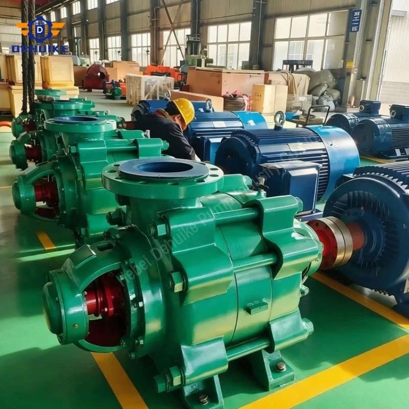
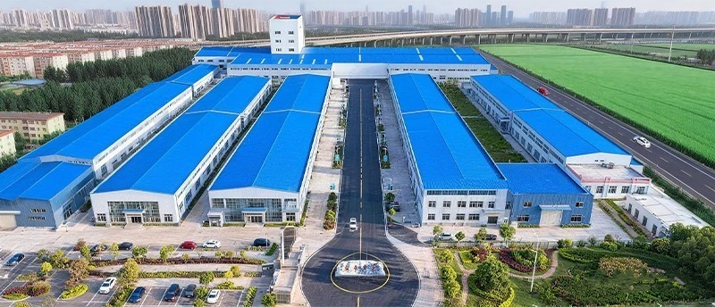
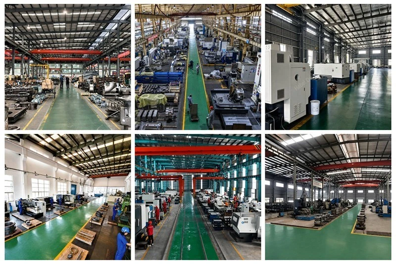
Dehuike Pump Industry integrates design and development, production and processing, sales and service. The company profile describes a process that includes raw material control, design, hydraulic model testing, casting, machining, inspection, assembly, testing, installation, commissioning, operation and after-sales service. For buyers, this supports communication from model selection through delivery and later service discussion.
The company profile states that Dehuike Pump Industry has more than 40 years of industry experience, develops and produces more than 30 series of industrial pump products, serves customers in more than 90 countries and has received ISO international quality management system certification. These facts support supplier evaluation while the final order still depends on the project-specific technical scope.
For a DA1 order, confirm the selected model, duty point, motor requirement, caliber, quantity, documents, packing method and delivery conditions before production. Clear confirmation reduces ambiguity and makes the final Horizontal Multistage Centrifugal Pump package easier to coordinate with contractors, distributors and end users.
Frequently Asked Questions
What is a Horizontal Multistage Centrifugal Pump?
It is a centrifugal pump that uses several hydraulic stages in a horizontal arrangement to develop the head required for clean-water supply or transfer. The DA1 series is used for factory and urban water supply duties where the system needs both controlled flow and higher delivery head.
Which DA1 models can be reviewed for medium water-supply duty?
The selected examples include DA1-80x9 at 32.4 m³/h and 102 m head, DA1-100x9 at 54 m³/h and 158 m head, and DA1-125x9 at 108 m³/h and 180 m head. Final selection depends on the calculated flow, total head, suction condition and installation layout.
Can the pump be selected only by head?
No. Head must be reviewed with flow, NPSHr, shaft power, motor power, efficiency, speed, caliber, water source and site installation conditions. A head-only selection may not match the actual system curve.
Is this pump suitable for boiler feedwater?
This page uses DA1 data for clean-water factory and urban water supply. Boiler feedwater projects should be reviewed with the applicable DG series data and boiler feedwater system requirements.
Why is NPSHr important?
NPSHr helps evaluate whether the suction side can support the selected operating point. The listed DA1 examples show NPSHr values from 2 m to 3.3 m. The available inlet condition should be checked before the final model is confirmed.
What information should be sent for quotation?
Send the required flow, total head, water source, suction details, electrical supply, operating schedule, pipe connections, site layout, quantity and documentation needs. This allows the DA1 Horizontal Multistage Centrifugal Pump to be reviewed against the real project duty.
How should replacement projects be handled?
Replacement projects should start with present operating data: pressure, estimated flow, motor load, water level, pipe size, operating hours and the reason for replacement. The new pump should be selected for the current system, not only for the nameplate of the old unit.
What makes the DA1 series useful for overseas buyers?
The DA1 series provides clear operating-point data and a conventional horizontal layout. Overseas buyers can compare flow, head, power, efficiency, NPSHr and caliber before confirming technical details, which helps reduce quotation uncertainty and installation risk.

Hot Tags: horizontal multistage centrifugal pump, China horizontal multistage centrifugal pump manufacturers, suppliers, factory