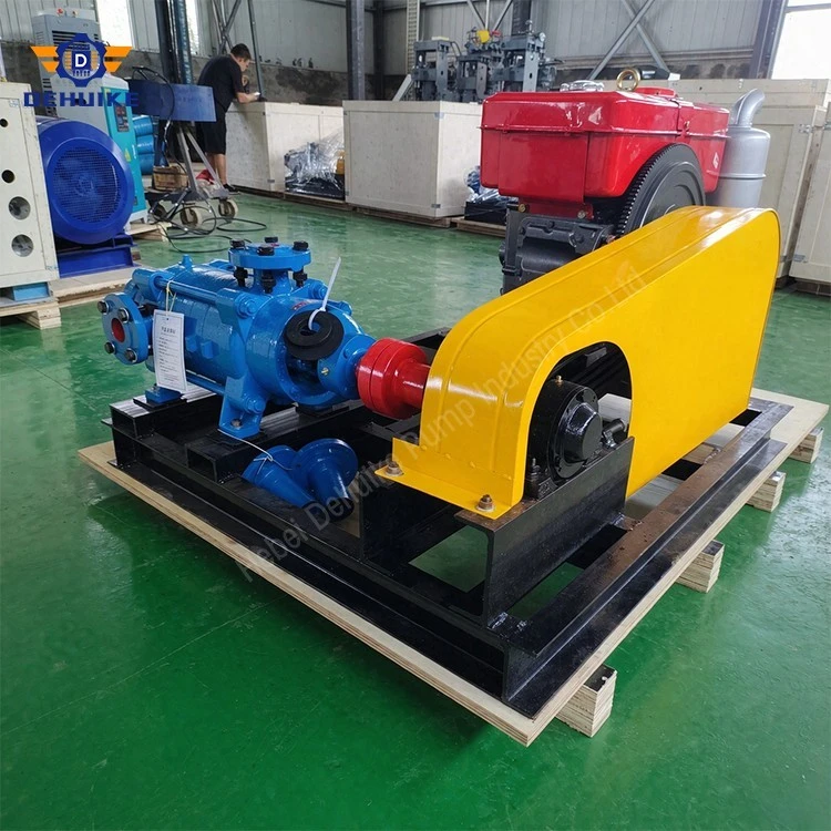
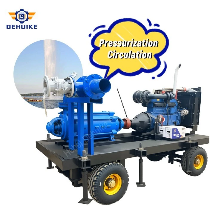
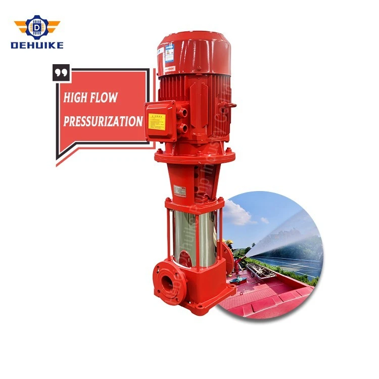
Hebei Dehuike Pump Industry Co., Ltd. is one of the most reliable manufacturers and suppliers of high pressure multistage water pump in China. With abundant experience, we are committed to providing high quality customized pumps with competitive price. Welcome to wholesale bulk high pressure multistage water pump for sale here from our factory. Also, pricelist is available.
Introduction
A buyer normally turns to a high pressure multistage water pump for one reason: the
discharge condition is too demanding for a single impeller at the required flow. In the DG
range discussed here, that condition sits between roughly 500 m and 960 m of head,
equivalent to about 49 bar to 94 bar of outlet pressure when the liquid is cold water.
Head and pressure express the same energy per unit mass in different units, and buyers
confuse them more often than any other pair of terms in pump selection. For water at 20 °C, 1
bar corresponds to about 10.2 m of water column. An 800 m duty is therefore close to 78 bar
at the discharge flange before any correction for temperature and density. Quoting a pump in
metres and a pipe class in bar, without converting between the two, is a frequent source of
mismatch at the commissioning stage.
Four decisions determine whether a high-head unit performs as intended: defining the
duty point, reading the model code and performance table, checking the power train, and
confirming suction and installation conditions. The figures quoted below are documented DG
performance values. They are reference points for comparison, not a replacement for a
project-specific selection.
The Discharge Condition Defines the Machine
Total head is the sum of four contributions: the static elevation difference between the
suction source and the discharge point, the pressure that must remain at the point of use, the
friction loss through pipe, fittings, filters, heat exchangers and valves, and a design margin. In
a low-head transfer line the static term normally dominates. In a high-head line the friction
term grows quickly with flow and often becomes the largest single component.
Because friction rises approximately with the square of flow, the duty point of a high-
head system reacts more sharply to a change in demand than that of a transfer system. A
modest increase in draw moves the intersection along a steep pump curve and changes
absorbed power with it. Sizing should therefore follow the real operating band - minimum,
normal and maximum flow - rather than a single peak figure copied from a process sheet.
Two further questions belong at this stage. Does the system need full pressure
continuously, or only during peak periods? And is the pressure set by a fixed process
requirement, or by a control valve that throttles? A process that throttles a fixed-speed pump
wastes energy and adds wear; one that varies speed to hold pressure needs a different motor
and control specification. Settling these points before a model is chosen is cheaper than
correcting them afterwards.
Residual pressure deserves separate attention. High-head installations occasionally
underperform not because the pump is small but because the receiving equipment needs 5 bar
to 10 bar at its inlet and that figure never reached the head calculation.
The Model Code Carries the Hydraulic Logic
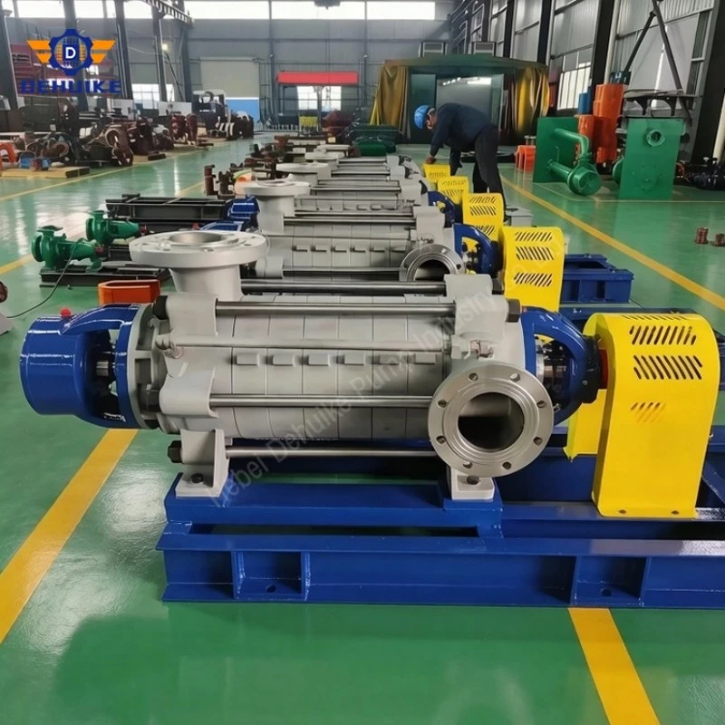
The DG designation follows a pattern worth learning, because it allows an engineer to
estimate head before opening a catalogue. A model such as DG85-80x12 reads in four parts:
DG is the series, 85 is the rated flow in m³/h, 80 is the head generated by a single stage in
metres, and 12 is the number of stages arranged in series.
Head consequently scales with stage count at almost constant flow. DG85-80x7 is listed
at 560 m and DG85-80x12 at 960 m, and 80 × 7 = 560 while 80 × 12 = 960. The same pattern
runs through the rest of the range: DG46-50x10 at 500 m, DG45-80x10 at 800 m, DG155-
67x8 at 536 m. Published values sometimes differ from a straight multiplication by a few
tenths of a metre because of interstage losses and impeller trimming, so the performance table
always governs the estimate.
This structure explains why multistage construction exists at all. One impeller large
enough to produce 900 m would need an exceptional diameter and peripheral speed, with
casings, seals and bearings to match. Dividing the head among smaller impellers keeps each
stage inside practical limits while the casing contains the accumulated pressure. The price is a
longer shaft, greater weight, and more sealing and bearing interfaces to look after.
It also explains what a buyer is really asking for when requesting "more pressure". A
higher stage count raises head at the same flow but increases shaft power, axial thrust, weight
and cost almost in proportion. A larger impeller raises head per stage but shifts the entire
curve. Neither change is a configuration option to be applied without rechecking the motor,
foundation, piping and relief protection.
Flow is a separate dimension, set by impeller passage geometry, eye area and speed
rather than by stage count. That is why the range contains distinct flow platforms - 45, 46,
85, 150 and 155 m³/h - each with its own ladder of stage options.
Documented Operating Points Across the Range
The six entries in Table 1 are published DG values chosen to show how head, power and
connections change through the high-pressure envelope. Each row is a complete operating
point for the model named. Interpolating between rows is not a substitute for reviewing the
curve.
Reading down the table separates flow from head. The 85 m³/h platform appears three
times: 560 m with a 275 kW motor, 670 m with 280 kW, and 960 m with 440 kW. Head rises
by 71% from the first of these to the last while flow stays unchanged, and motor rating rises
by 60%. That ratio is the practical cost of adding stages.
Reading across a row shows why a model number alone is an incomplete offer. NPSHr
between 2.8 m and 5.5 m, efficiency between 55% and 74%, and connections from DN80 to
DN150 all belong to the specific point listed. The same pump can be quoted against
noticeably different flows, and the buyer should insist that the proposed point matches the
duty.
The 45 m³/h and 155 m³/h entries mark the ends of the useful band. DG45-80x10 reaches
800 m with a 220 kW motor and an 80/65 mm connection set, while DG155-67x8 delivers
536 m at 155 m³/h with 355 kW and 150/150 mm connections. Both are high-pressure
machines, yet the pipework, foundation and electrical work they require have very little in
common.
From Hydraulic Power to a Motor Rating
Hydraulic power follows directly from flow and head: \(P=\rho g Q H / 3,600,000\) , with Q in \(m^{3} / h\) in m³/h, H in metres and P in kW. For water at normal density the expression simplifies to approximately Q × H / 367.
he check works in both directions. Take DG85-67x10: 85 × 670 / 367 gives about 155
kW of hydraulic power. The listed shaft power is 238.5 kW, a ratio of 65%, which is exactly
the efficiency printed for that row. The same arithmetic on DG45-80x10 returns 98 kW
against 178.3 kW, or 55%, again matching. An offer whose shaft power and efficiency do not
reconcile in this way is worth questioning before the order is confirmed.
Motor rating is not absorbed power. The table pairs 238.5 kW of shaft power with a 280
kW motor, and 341.76 kW with 440 kW. The gap covers impeller manufacturing tolerance,
voltage and frequency variation at site, small changes in density or temperature, and the fact
that a motor held near its nameplate rating for years has no reserve left. The margin should be
agreed rather than assumed: too small a motor overheats, while an unnecessarily large one
runs at a poor load factor.
Starting method carries more weight at this head than at low-head duty. A high-head
centrifugal pump draws a heavy current during a direct-on-line start and reaches a high
shutoff head before the check valve lifts. Soft starting or a variable-frequency drive reduces
the electrical shock and allows a controlled run-up. Whichever method is chosen, shutoff
pressure must be compared with the rating of the discharge pipe, valves and any downstream
vessel.
Where demand varies, speed control is the efficient answer, and the affinity relationships
are the tool for estimating its effect: flow changes with speed, head with the square of speed,
power with the cube. A 20% speed reduction cuts power by roughly half. That estimate holds
only while the system curve keeps its original shape and the pump stays above a sensible
minimum speed, so it should be confirmed on the actual curve instead of applied as a rule.
Boiler Feedwater Use: What Buyers Should Verify
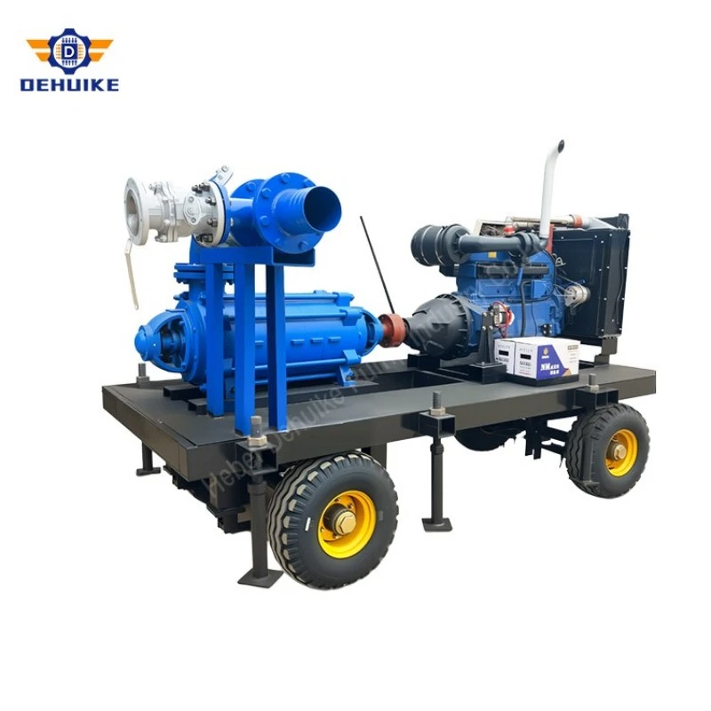
Boiler feedwater service is one of the common reasons buyers ask for a high pressure multistage water pump. The pump must deliver water into a pressurized circuit and often works under continuous or frequent-duty conditions. Selection should consider boiler pressure, control-valve loss, deaerator or tank level, water temperature, minimum flow protection, standby arrangement, and the way the boiler system responds to changing demand.
A pump may meet the listed head but still be unsuitable if suction margin is weak or if control logic forces operation at unstable low flow. For boiler-related inquiries, provide the boiler operating pressure, required feedwater flow, water temperature, suction tank arrangement, and expected duty cycle. This allows the supplier to judge whether the model and accessories fit the real feedwater package.
Suction Conditions and NPSH
The NPSHr values in Table 1 range from 2.8 m to 5.5 m. They state the suction
condition the pump needs at the listed point; they say nothing about what the installation
supplies. NPSHa is calculated on site from the absolute pressure at the suction source, the
vapour pressure of the liquid at its operating temperature, the height of the liquid surface
above the pump, and the friction loss in the suction line and strainer.
Temperature changes that calculation more than most buyers expect. The vapour
pressure of water climbs steeply as it approaches boiling, so a feedwater line at 105 °C has far
less available NPSH than the same line at 40 °C. In boiler feed service the deaerator height
and the temperature maintained there are usually the controlling factors, and both are fixed
long before the pump is ordered.
A working margin should be kept between NPSHa and NPSHr, commonly 0.5 m to 1 m
at the design point, and it should be checked at the worst credible condition: lowest tank level,
highest temperature, a partly blocked strainer, and maximum flow. Cavitation rarely appears
at the point used for selection. It appears on the day the strainer is dirty and the level is low.
Suction piping belongs to the same subject. A long, undersized or poorly vented suction
line consumes the margin the calculation allowed. Air pockets, unnecessary bends and a
horizontal run with a high point create problems no pump can correct afterwards.
Applications That Call for This Head Level
Medium and low pressure boiler feed is the classic application. Feedwater must enter a
pressurised circuit at a controlled rate, and the pump has to overcome boiler pressure together
with the losses in the feed line, economiser and control valve. Selection depends on the
boiler's design pressure and evaporation rate, the deaerator arrangement and the turndown
required. A boiler that runs at low load for long periods needs a pump whose curve remains
stable in that region.
Plant water networks use this head level when water must reach elevated consumers,
cross long pipe corridors or feed a pressurised header serving several departments. Friction
dominates the system curve, and the network often grows as the plant expands. A pump
chosen only for today's peak can end up far to the left of its curve once a line is extended.
High-pressure water is also used at the point of use rather than through a network:
descaling, washing, filter and membrane feed, cooling of equipment in tall structures, and
injection into a process at pressure. Each has its own cleanliness, temperature and material
requirement, and those requirements usually decide the construction rather than the hydraulics.
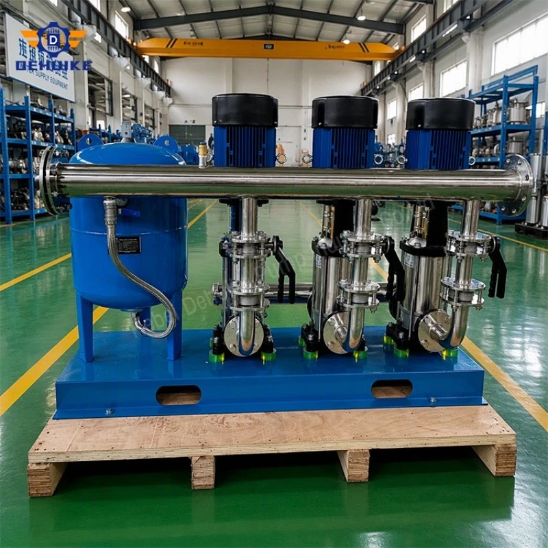
Closed loops and pressurisation skids use a high-head unit to hold pressure against
expansion and small leakage rather than to move large volumes. In that role the pump spends
much of its time at low flow, so minimum-flow protection, bypass arrangement and control
logic matter as much as the head rating.
Hot Tags: high pressure multistage water pump, China high pressure multistage water pump manufacturers, suppliers, factory