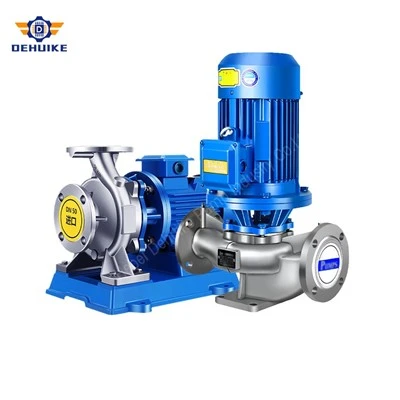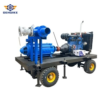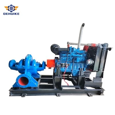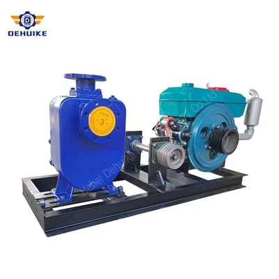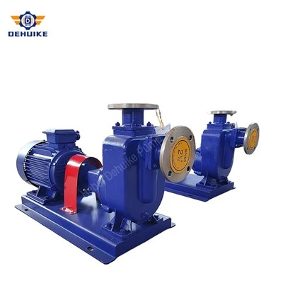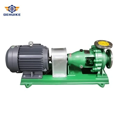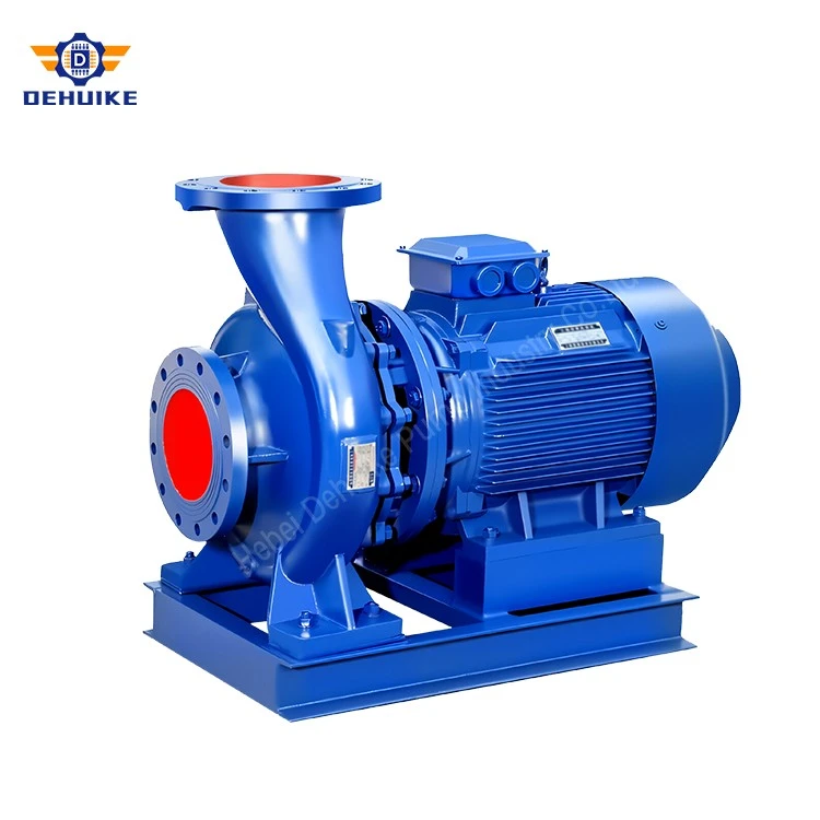
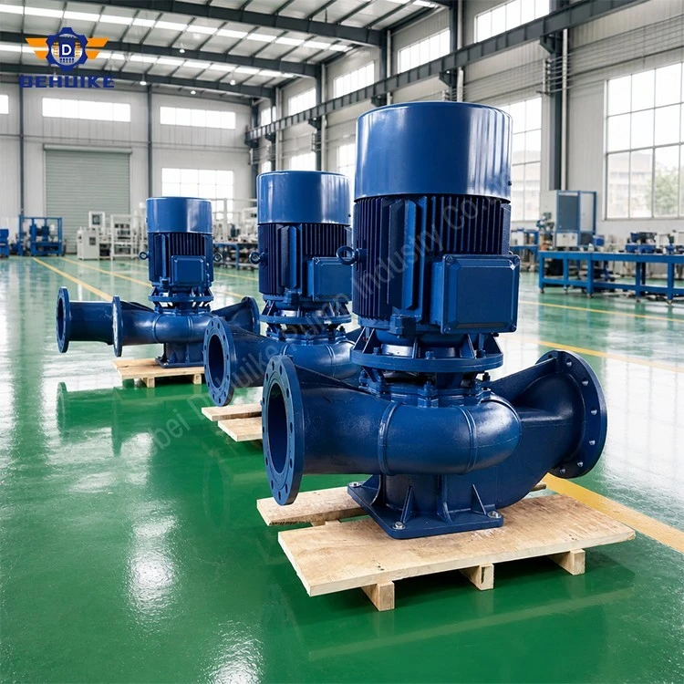
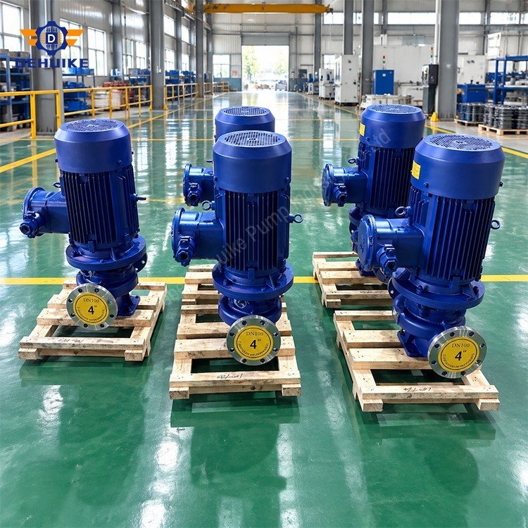
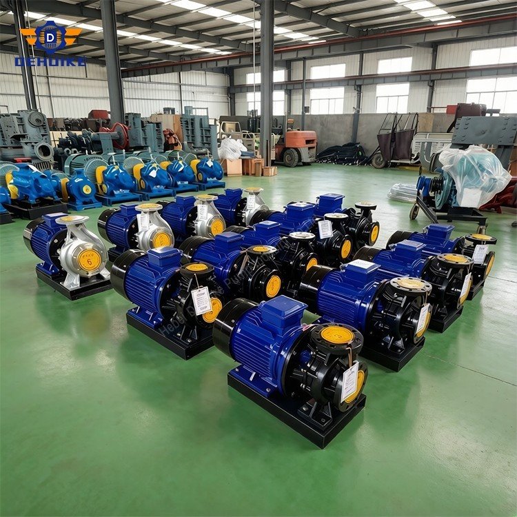
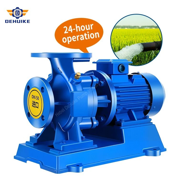
Hebei Dehuike Pump Industry Co., Ltd. is one of the most reliable manufacturers and suppliers of vertical inline centrifugal pump in China. With abundant experience, we are committed to providing high quality customized pumps with competitive price. Welcome to wholesale bulk vertical inline centrifugal pump for sale here from our factory. Also, pricelist is available.
Field Realities of Plant Footprints & Pipework Geometry
Anyone who has walked through a crowded central chiller room or a high-rise booster station knows what real estate costs inside a building. Floor space in utility basements often runs hundreds of dollars per square foot to excavate and waterproof. When mechanical plans call for three or four large horizontal frame pumps, the piping layout quickly becomes a headache. You need sprawling concrete housekeeping pads, heavy inertia blocks, and long pipe elbows just to turn incoming headers ninety degrees into the suction nozzles and then another ninety degrees back out. That extra pipework burns pressure, adds dozens of bolted joints, and leaves almost zero walkable clearance for technicians carrying toolboxes.
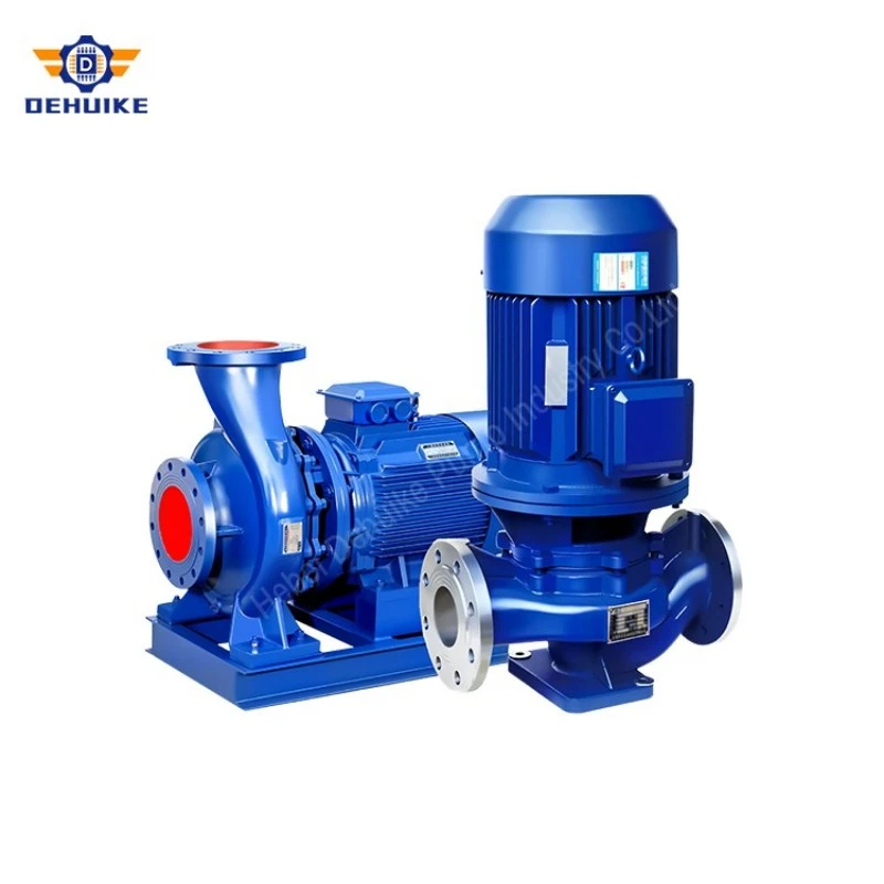
That exact field headache is why mechanical designers specify our Vertical Inline Centrifugal Pump. Instead of sprawling across the concrete, an in-line unit sits directly inside the run of pipe like a flanged gate valve. Suction and discharge share the same diameter, face each other on the exact same centerline, and take up only the width of the pipe spool itself. You cut out the offset elbows, throw out the massive concrete inertia blocks, and recover valuable floor acreage. For retrofits where an older building needs expanded pumping capacity inside an existing, unyielding mechanical room, dropping in a Vertical Inline Centrifugal Pump is often the only way to double flow without knocking down structural walls.
Underneath the cast iron casing, the fluid dynamics solve another major field headache: keeping operating kilowatts under control. Fluid enters horizontally, turns smoothly through an engineered guide contour into the eye of an enclosed radial impeller, and discharges straight out the opposite flange through a continuously expanding volute channel. By keeping fluid transitions gradual and symmetrical, internal hydraulic recirculation drops right off. The machine runs right along its Rated Optimal Efficiency Point (BEP), pulling fewer amps on the motor nameplate while delivering clean, non-surging head into distribution mains.
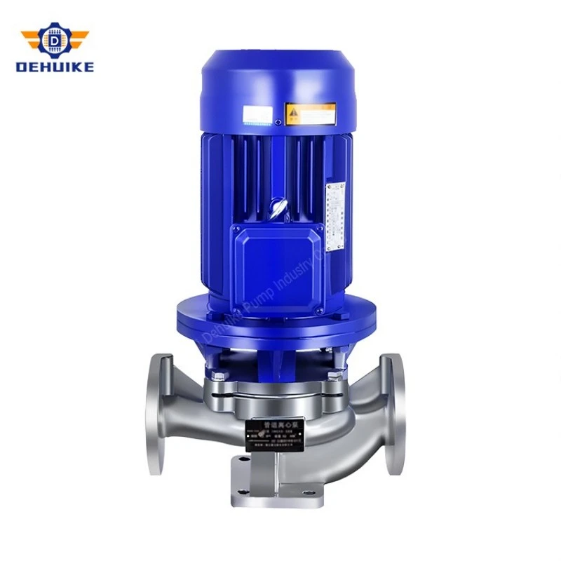
Reliability on site comes down to basic mechanical physics. With the drive motor standing upright over the wet end, gravity works in your favor rather than against you. Shaft deflection stays virtually zero because the impeller does not hang on a long horizontal cantilever. Flooded pump trenches, pipe condensation, and valve packing drips stay well away from electrical junction boxes and motor bearings. You get an industrial Vertical Inline Centrifugal Pump that pipefitters can bolt in place before lunch and maintenance crews can service for decades without tearing apart the piping.
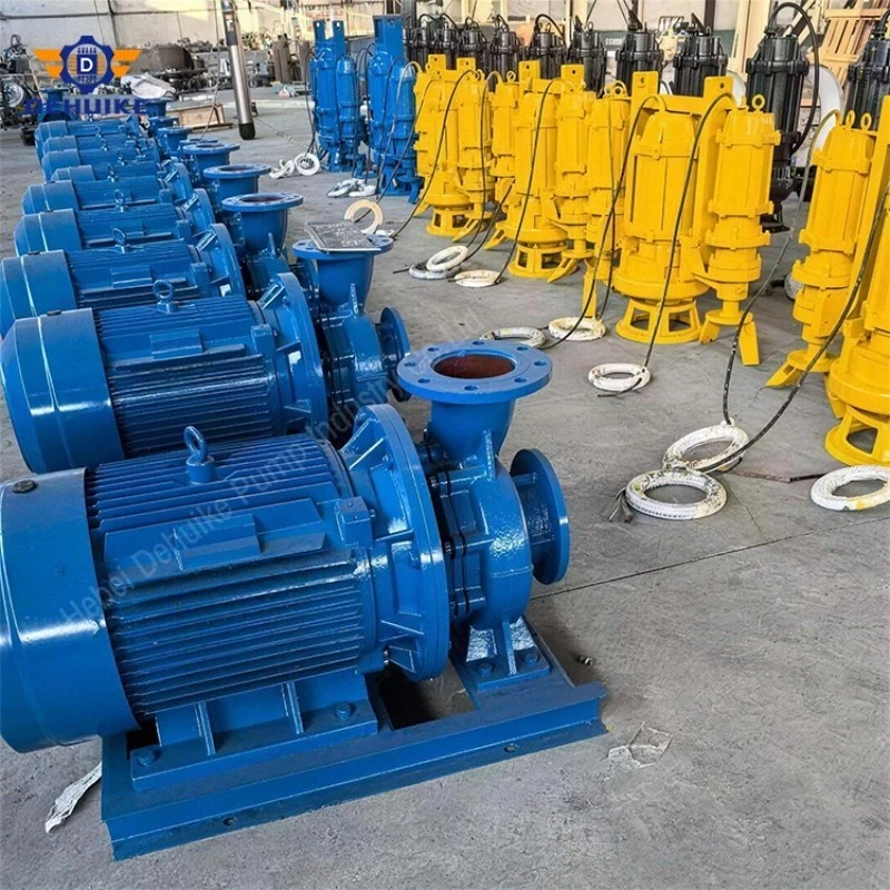
Features & Equipment Characteristics: Mechanical Architecture of the In-Line Build
Taking a wrench to a pump in a cramped plant room shows you quickly whether it was designed by a draftsman who never left his desk or by engineers who understand dirty hands. Every casting, register spigot, and bolt circle on this Vertical Inline Centrifugal Pump series reflects practical field priorities.
True Coaxial In-Line Flange Orientation: Suction and discharge nozzles are cast on the same horizontal plane at 180 degrees to each other, matching standard DIN or ANSI center-to-face dimensions. Pipefitters can weld up straight headers, drop isolation valves and strainers in a clean row, and bolt the casing right into position. The straight geometry eliminates piping eccentricities, minimizes thermal stress transfer from expanding headers, and lets the pipeline carry a significant share of static equipment mass.
Top-Pullout Back Disassembly Architecture: When a mechanical seal reaches the end of its service life or an impeller needs inspection, nobody wants to unbolt pipe flanges. With our top-pullout build, the pump volute stays untouched in the piping. A mechanic unfastens the main casing cover nuts, lifts the motor and intermediate adapter stool straight upward using a chain fall, and walks the entire rotating element over to the workbench. Flange gaskets, suction strainers, and pipe alignments stay completely undisturbed.
Rigid Cast Adapter Stool & Motor Pilot Alignment: Misalignment kills mechanical seals faster than dirty water ever will. Instead of relying on thin fabricated brackets and shims, our pump uses a heavy-section cast iron motor stool. The bottom face registers against a CNC-machined rabbet fit on the casing cover, while the top face locks directly into the motor's D-flange spigot. This rigid, metal-to-metal concentric pilot guarantees that the motor shaft, shaft sleeve, and seal face sit within 0.02 mm of true center without needing laser alignment tools or dial indicators on site.
Direct-Drive Coaxial Shaft Rigidity: By eliminating flexible elastomeric spider couplings and long jack shafts, the impeller mounts securely to a rigid shaft arrangement with minimal overhang. The distance from the lower motor bearing to the impeller centerline is kept exceptionally short. Less overhang means virtually zero shaft whip under partial-flow turbulence, preventing the micro-deflections that cause mechanical seal faces to chip and leak.
Integral Seal Chamber Atmospheric Drainage: Beneath the mechanical seal seat, the cast stool incorporates an open atmospheric drain cavity. If a mechanical seal begins weeping after thousands of operating hours, tell-tale fluid drains cleanly out the bottom port into an open drain funnel. Fluid cannot migrate upward past the motor slinger ring into the lower motor ball bearings, preventing catastrophic electrical shorts and winding washouts.
Reinforced Casing Base Pad for Optional Floor Support: Smaller units (DN40 to DN65) hang safely supported by adjacent pipe hangers. For heavier units (DN80 to DN150), the bottom of the volute casting features an integral, flat-machined mounting foot drilled with anchor bolt holes. Plant crews can set the pump on a simple steel channel skid or small concrete pedestal, providing solid vertical foundation support without absorbing pipeline expansion forces.
Specifications & Technical Parameters: Verified Engineering Duty Matrices
Selecting an in-line circulator requires hard numbers, not sales promises. Our factory product line spans standard pipe diameters from DN50 up to DN200. Standard pressure casings carry a conservative PN16 hydrostatic rating, meaning they comfortably handle sixteen bar (1.6 megapascals) continuous working line pressure at temperatures from sub-zero conditions up to warm hydronic limits. For district heating loops, optional high-grade seal flush plans push fluid thresholds to 120°C.
The technical values in Table 1 come directly from logged data in our certified plant testing archives. Each line lists rated design capacity, head at duty point, measured hydraulic efficiency, motor shaft speed, motor kilowatt rating, required suction head (NPSHr), and total dry mass across compact, mid-size, and heavy industrial configurations.
Table 1: Verified Duty Ratings for Key Industrial Vertical Inline Models
|
Model Code |
Flange Bore |
Rated Flow |
Total Head |
Hydraulic Eff. |
Shaft Speed |
Motor Power |
NPSHr Head |
Dry Mass |
|
ISG-50-200B |
DN50 |
15.2 m³/h |
40.0 m |
55 % |
2900 r/min |
4.0 kW |
2.5 m |
100 kg |
|
ISG-65-200B |
DN65 |
30.5 m³/h |
40.6 m |
65 % |
2900 r/min |
7.5 kW |
3.0 m |
114 kg |
|
ISG-80-125A |
DN80 |
62.6 m³/h |
19.0 m |
68 % |
2900 r/min |
7.5 kW |
4.5 m |
113 kg |
|
ISG-80-125H |
DN80 |
70.0 m³/h |
23.5 m |
70 % |
2900 r/min |
11.0 kW |
4.5 m |
163 kg |
|
ISG-100-200B |
DN100 |
61.0 m³/h |
41.0 m |
71 % |
2900 r/min |
15.0 kW |
4.0 m |
193 kg |
|
ISG-100-200H |
DN100 |
96.0 m³/h |
53.0 m |
69 % |
2900 r/min |
37.0 kW |
5.2 m |
402 kg |
|
ISG-125-160A |
DN125 |
96.0 m³/h |
36.0 m |
78 % |
2900 r/min |
22.0 kW |
4.0 m |
265 kg |
|
ISG-125-160B |
DN125 |
83.0 m³/h |
27.0 m |
73 % |
2900 r/min |
15.0 kW |
4.0 m |
215 kg |
|
ISG-150-160A |
DN150 |
96.0 m³/h |
36.0 m |
75 % |
2900 r/min |
22.0 kW |
4.0 m |
270 kg |
|
ISG-150-160B |
DN150 |
84.0 m³/h |
27.0 m |
73 % |
2900 r/min |
15.0 kW |
4.0 m |
220 kg |
Looking at these duty points gives plant engineers clear sizing boundaries. For branch hydronic loops and secondary chilled circuits, the 50-200B and 65-200B push 15 to 30 cubic meters per hour against 40 meters of head with modest electric drives. When you move to primary cooling circuits and main plant headers, the 100-200H and 125-160A deliver high-volume throughput-reaching 96 m³/h with peak efficiencies hitting 78 percent. That efficiency number is vital: on a 22 kW motor running 8,000 hours a year, a three-point jump in hydraulic efficiency saves thousands of dollars in utility billing, easily outpacing the initial purchase price of the machine within twenty-four months.
Product Details & Metallurgy: Materials, Shaft Concentricity & Sealing Configurations
A pump is only as dependable as the raw iron poured into its mold and the precision of the wear surfaces inside its seal chamber. We don't cut corners with recycled scrap mixtures or unbranded component seals. Every metal alloy and elastomer compound is chosen for predictable wear resistance and corrosion durability under real plant conditions.
Casing & Impeller Metallurgy: Standard pump casings and top covers are cast from HT200 or HT250 close-grained pearlitic gray iron. The material has excellent vibration-damping properties, absorbing hydraulic hum before it travels down the pipe. For systems handling mild chemical treated water or operating at working pressures above 1.6 MPa, we pour ductile iron QT450-10, which provides superior tensile strength and impact toughness. Impellers are cast in balanced gray iron, tin bronze (ZCuSn10Pb1), or investment-cast 304/316 stainless steel depending on fluid salinity and corrosive potential.
Heavy-Gauge Stainless Shaft & Precision Sleeve: The drive shaft extension is machined from heat-treated 2Cr13 stainless alloy, refined to an elevated yield strength to handle sudden torque spikes during across-the-line starts. In the packing box zone, a replaceable 304 sleeve slips over the core shaft. The outer diameter is ground to a mirror finish (Ra < 0.4 μm) where it contacts the mechanical seal bellows, eliminating grooving and preventing corrosive fluid contact with the drive core.
Industrial Cartridge & Component Mechanical Seals: Leak-free operation rests on the mechanical seal. Standard clean water models come fitted with silicon carbide versus resin-impregnated carbon faces running against an EPDM secondary O-ring. Silicon carbide provides high hardness to resist fine pipe scale and suspended rust particles, while the carbon face provides lubricity during brief flow fluctuations. For closed loops carrying glycol antifreeze, we upgrade seal faces to SiC versus tungsten carbide pairing, backed by peroxide-cured FKM (Viton) elastomers that resist chemical swelling.
Replaceable Casing Wear Rings & Running Clearances: To prevent high-pressure discharge liquid from blowing back toward the impeller intake throat, the casing houses precision-machined wear rings. Diametrical clearance between the impeller neck and wear ring is maintained between 0.25 mm and 0.35 mm. By confining fluid erosion to these sacrificial wear rings, the expensive volute casting remains protected. When clearance widens after years of operation, a technician simply replaces the inexpensive ring to restore initial hydraulic pressure and efficiency.
Production Process: Foundry Pouring, CNC Turning & Shop-Floor Assembly
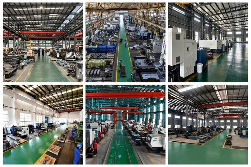
Walk our shop floor and you will see how tight manufacturing controls keep defective parts from ever reaching the assembly benches. Quality in fluid machinery is built during molding, machining, and balancing-not inspected in at the very end.
Resin-Sand Mold Preparation & Spectrographic Melt Testing: We mold all casings and motor stools using furan resin bonded sand rather than traditional wet green sand. Resin sand holds exact core dimensions under the thermal shock of molten iron, yielding smooth hydraulic waterways free from sand inclusions, scab defects, and wall-thinning voids. Before the ladle leaves the electric induction furnace, an optical emission spectrometer reads carbon, silicon, manganese, and phosphorus levels. If the carbon equivalent is off by half a percent, the melt stays in the pot until chemistry matches our metallographic standard.
Thermal Stress Annealing Cycle: Freshly shaken-out castings carry significant internal stress from uneven cooling between thick flange bosses and thin volute cutwaters. We stack rough castings into a computerized heat-treatment furnace, ramp temperatures slowly to normalization levels, hold for four hours, and cool gradually down to ambient. Relieving internal stresses prevents castings from twisting out of square when machinists shave metal off the flange faces, ensuring joints stay dead flat and leak-free under bolted pipe loads.
Single-Clamping CNC Multi-Axis Machining Centers: Machining is carried out on heavy vertical and horizontal CNC machining centers. The cast pump body clamps inside a heavy fixture where boring heads machine the suction flange, discharge flange, internal wear ring counterbore, and top cover spigot in one continuous program. Because the workpiece never unclamps between operations, squareness between the vertical motor register and horizontal pipe axis is held inside twenty microns. You get identical flange bolt circles that line up effortlessly with jobsite piping.
Dual-Plane Impeller Dynamic Balancing: Every cast impeller is balanced dynamically on an electronic hard-bearing balancing machine to Grade G2.5 per ISO 1940 dynamic limits. The balancing rig rotates the trimmed impeller at rated speed, reads dynamic force vectors at both shrouds, and prompts the operator to mill material cleanly off the outer shroud rim until residual unbalance is driven below gram-millimeter thresholds. Balanced impellers eliminate radial shake that ruins motor bearings and rattles mechanical room ceiling hangers.
Hydrostatic Proof Testing at Twenty-Four Bar: Before any paint or assembly, 100% of raw machined casings are clamped into a high-tonnage hydraulic test rig. Blind flanges seal the ports, air is purged, and treated water is pressurized to twenty-four bar (2.4 megapascals, or 150% of nominal pressure) for fifteen continuous minutes. Pressure sensors log the holding curve. Any casting showing pressure drops, micro-sweat on the wall, or flange weeping is rejected immediately.
Centrifugal Shot-Blasting & Industrial Polyurethane Enamel: Clean metal holds paint; dirty metal flakes. Assembled casings enter an automatic shot-blast booth where steel grit strips all foundry scale to an Sa 2.5 profile. Castings then receive a high-solids two-part epoxy primer followed by an industrial polyurethane enamel topcoat cured under infrared lamps. The resulting coating withstands wet mechanical room humidity, sweaty pipe dripping, and chemical washdowns without peeling or rusting.
Quality Assurance: Physical Hold Points & Hydraulic Verification Standards
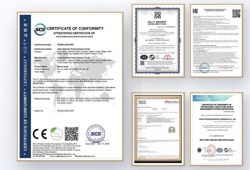
We operate an uncompromising quality assurance system governed by ISO 9001 certified protocols. Every Vertical Inline Centrifugal Pump manufactured in our plant follows a traveler document that moves from foundry shakeout to crate loading, requiring inspector sign-offs at critical hold points before moving to the next bay.
Incoming Raw Material Chemistry & Tensile Verification: Foundry pig iron, scrap steel charges, and alloy additives are quarantined until metallurgical lab tests confirm chemistry. Tensile test bars poured from each furnace heat undergo destructive pull testing on an electronic universal tensile tester, verifying minimum tensile strengths of 200 MPa for HT200 and 450 MPa for QT450. Component hardware, including 8.8-grade casing studs and high-tensile flange fasteners, must present mill test certificates before entering parts bins.
Coordinate Measuring Machine (CMM) Dimensional Audits: First-piece inspections from CNC machining bays undergo dimensional verification on a bridge-type coordinate measuring machine. Critical dimensions-including casing spigot registers, mechanical seal chamber runout, impeller bore tolerances, and flange bolt pitch circle diameters-must stay strictly within ISO tolerance tables. Machining tools are reset before dimensional drift can compromise assembly fits.
Full-Scale Hydraulic Performance Testing to ISO 9906 (Grade 2B): Our factory houses a fully digitized closed-loop hydraulic test station with calibrated magnetic flowmeters, piezo transmitters and electromagnetic flow meters. Every batch of assembled pumps undergoes full-speed testing across five distinct duty points: shut-off head, minimum continuous flow, Rated Optimal Efficiency Point (BEP), design flow, and maximum run-out capacity. If head or efficiency falls outside ISO 9906 (Grade 2B testing protocol) tolerances, the unit goes back for impeller trim analysis.
Vibration Spectrum & Bearing Temperature Monitoring: During the hydraulic test run, triaxial piezoelectric accelerometers mount to the motor bearing housings to record velocity vibration spectra across overall frequency ranges. Total vibration velocity must remain well below 2.8 mm/s RMS (conforming to ISO 10816-3 Class I and II standards). Motor bearings are run until temperature stabilization to confirm lubricant distribution and verify that running temperatures remain well below thermal thresholds.
EAC & RoHS International Environmental Compliance: Beyond ISO 9001 quality audits, our product lines carry official EAC compliance papers for customs trade and RoHS certification confirming the strict elimination of hazardous heavy metals, lead solder, and toxic plasticizers. Whether shipping to a district heating utility in Central Asia or a hospital mechanical room in Europe, our documentation packages satisfy local regulatory inspections on arrival.
Application Engineering: Field Deployments Across Commercial & Industrial Loops
Because this Vertical Inline Centrifugal Pump model integrates space-saving inline geometry with heavy-duty pressure containment, plant engineers rely on our machines across thousands of commercial installations and industrial processing networks. The following installation sectors highlight where this machinery delivers exceptional day-to-day service.
Commercial HVAC Central Plant Chiller Loops & Cooling Towers: In high-rise corporate towers, luxury hotel resorts, and international airport terminals, central chiller plants cannot afford downtime during sweltering summer peaks. Bolted directly into header runs, our pumps move supply loops chilling water between six and twelve Celsius through plate chillers and primary distribution risers, while adjacent units circulate warm condenser water out to rooftop cooling towers. The inline geometry lets contractors mount multiple pumps in a tight parallel battery, keeping isolation valves and check valves in a clean, accessible line.
Mission-Critical Enterprise Data Center Liquid Cooling: High-density server racks generate extreme heat fluxes that air handlers alone cannot remove. Hyperscale data centers rely on closed-loop fluid heat-rejection circuits and computer room air handlers (CRAH) operating 24 hours a day, 365 days a year. Our dynamically balanced impellers deliver exceptionally low vibration velocity, preventing structural vibration from traveling down piping into sensitive hard drive arrays while keeping server supply temperatures rock steady.
High-Rise Secondary Potable Water Pressure Boosting Skids: Structures over twenty stories cannot supply upper residential or office floors directly from municipal water mains without exceeding safe fixture pressures on ground floors. Packaged multi-pump skid assemblies incorporate our in-line pumping units tied to variable frequency drives, taking head from intermediate buffer reservoirs and pushing steady domestic water pressure to upper zones without water hammer or cavitational pipe noise.
Municipal District Energy Substations & Primary Heating Circuits: In municipal heating grids with central thermal hubs, pressurized hot water mains feed localized basement energy transfer stations. Our vertical units circulate hot water through brazed plate heat exchangers into building radiator and underfloor hydronic circuits. Rugged cast iron volutes and temperature-isolated motor stools handle winter thermal expansion effortlessly without causing seal leaks or motor bearing overheating.
Industrial Process Cooling & Factory Tool Hydronics: Industrial plants running plastic injection molding machines, induction annealing furnaces, metal die-casting presses, and laser cutting tables require dependable closed-loop cooling water. Mineral scaling and thermal cycling punish weak pumps. Our heavy-section volutes, stainless steel shaft sleeves, and silicon carbide face rings shrug off dirty factory cooling water, preventing unexpected production stops that cost thousands of dollars per hour.
Our Advantages & Foundry Heritage: Manufacturing Scale, Supply Ecosystem & Warranty Assurance
In the B2B industrial equipment sector, a product catalog is only as strong as the manufacturing infrastructure behind it. Purchasing agents, contracting engineers and regional distributors choose Hebei Dehuike Pump Industry Co., Ltd. because our manufacturing scale, commercial transparency, and engineering support deliver long-term peace of mind.
Three Decades of Continuous Fluid Equipment Manufacturing: We have spent three continuous decades of specialized pump making focused on heavy industrial fluid machinery. That long manufacturing history means our hydraulic patterns, casting methods, and shaft tolerances are grounded in thousands of real-world installations. We know where castings tend to wear, how motor stools behave under hydraulic shock, and how to build equipment that survives tough industrial duties.
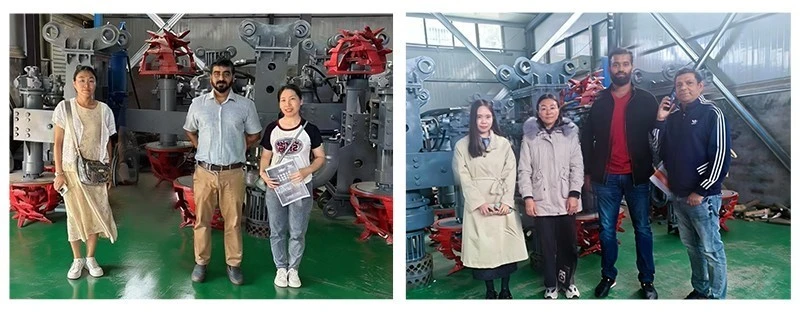
Production Base Exceeding Six Thousand Square Meters: Our main manufacturing complex covers a six-thousand-plus square-meter shop floor (6,000 m²). The plant houses dedicated resin-sand molding bays, multi-axis CNC machining lines, climate-controlled mechanical seal assembly rooms, dynamic balancing stations, automated finishing booths, and an instrumented hydraulic test sump, handling high-volume flows peaking at 2,500 m³/h.
Resilient Supplier Ecosystem with Over 900 Vetted Partners: Stable production lead times require resilient raw material pipelines. We work closely with an ecosystem of over nine hundred qualified regional suppliers. From varnished copper stator windings, sintered carbide face rings, and heavy-duty NSK/SKF drive bearings, our supply integration ensures component consistency, rapid turnaround, and dependable production schedules even during global market supply chain crunches.
Twenty-Four Months of Comprehensive Mechanical Warranty: We provide twenty-four months of full factory warranty protection, protecting the entire mechanical unit (excluding standard wear components). While standard trading companies and smaller assemblers offer only twelve months, our extended warranty underscores our complete assurance in our casting quality, CNC machining tolerances, and rigorous shop-floor inspection protocols.
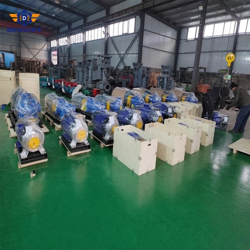
Global Distribution Footprint in Over Fifty Export Destinations: Our equipment has been deployed across over fifty export destinations globally. We handle international export logistics professionally, packaging equipment in ISPM 15 heat-sterilized wooden packing cases. Internal machinery surfaces receive vapor-phase corrosion inhibitors and heavy-gauge moisture barrier vacuum wraps.
Transparent Multimodal International Trade & Freight Handling: We quote standard international commercial trade terms under FOB terms or CIF terms delivered directly to buyer-designated arrival seaports. For emergency maintenance shutdowns and urgent replacement parts, we organize fast air courier for spare kits (50–500 kg weight band). For routine project volumes and large volume ocean shipments weighing over 500 kilograms, shipments are managed via standard maritime container vessels with full tracking papers.
Direct Manufacturer Commercial Access & Dedicated Engineering Channel: By dealing directly with our corporate export and technical divisions, buyers avoid intermediary trading markups and communication delays. You speak straight to knowledgeable pump specialists who understand system head calculations, motor voltages, and delivery schedules. For technical tenders, selection curve confirmations, or commercial inquiries, reach out to our engineering trade desk at director@dhkpump.com or telephone +86 19503223662.

Hot Tags: vertical inline centrifugal pump, China vertical inline centrifugal pump manufacturers, suppliers, factory