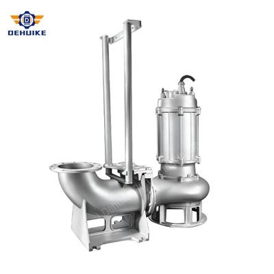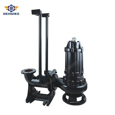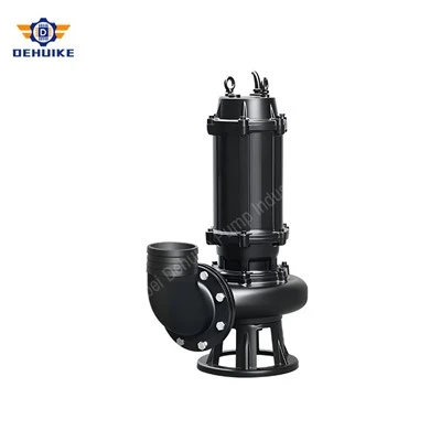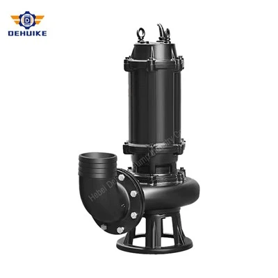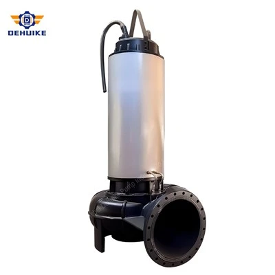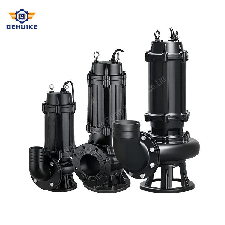
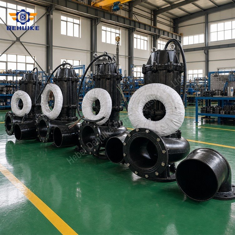
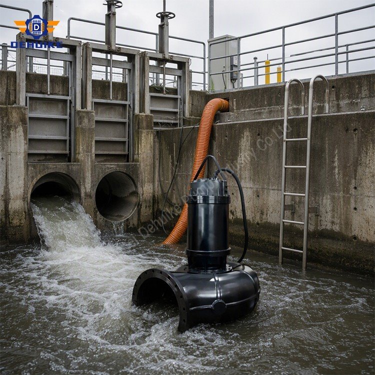
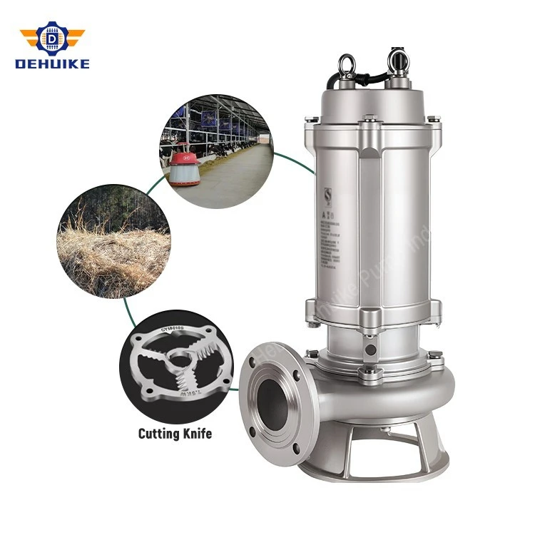
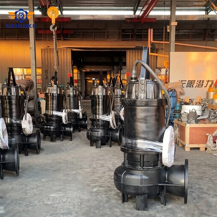
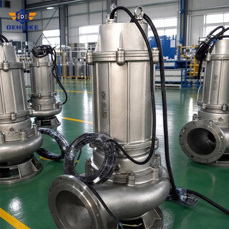
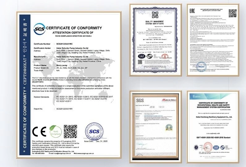
Hebei Dehuike Pump Industry Co., Ltd. is one of the most reliable manufacturers and suppliers of non-clogging submersible sewage pump in China. With abundant experience, we are committed to providing high quality customized pumps with competitive price. Welcome to wholesale bulk non-clogging submersible sewage pump for sale here from our factory. Also, pricelist is available.
How the Hydraulic Passage Resists Clogging
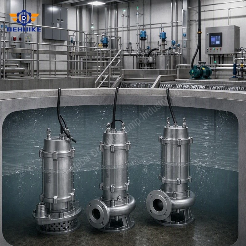
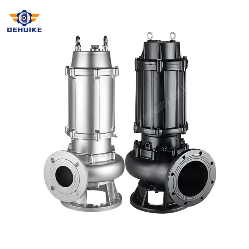
A non-clogging submersible sewage pump is a solids-handling pump built to move wastewater that may contain rags, fibers, soft debris and suspended particles without requiring a surface pump room. The pump works below liquid level, so the wet well supplies flooded suction at start-up. Its defining difference is not simply that it is submersible: the hydraulic passage, impeller entrance and discharge geometry are coordinated to reduce the places where flexible material can wrap, bridge or lodge.
For a buyer, "non-clogging" should be treated as a design objective rather than an unlimited promise. No centrifugal sewage pump can safely pass every object that enters a sewer. Correct performance depends on the actual solids profile, the free passage through the selected hydraulic, the duty point and the operating cycle. A pump chosen for screened effluent may not suit unscreened inlet sewage containing wipes or long fibers. The first technical conversation should therefore describe the waste stream, not only quote flow and head.
Wide-entry hydraulic path. The flow entrance should guide liquid and solids into the rotating element with limited recirculation. A generous eye area lowers local velocity peaks that can pin material against the suction edge. Smooth transitions from inlet to volute reduce shelves where sediment settles during standby periods.
Vane count matched to solids behavior. Fewer flow channels generally provide larger individual passages, while multi-channel arrangements can provide a different balance of hydraulic efficiency and solids passage. The appropriate choice depends on whether the liquid carries bulky soft solids, dispersed fibers or predominantly fine suspended matter.
Recessed or channel-style alternatives. A recessed-flow hydraulic keeps much of the conveyed material away from the rotating passages and may be preferred where stringy debris dominates. A channel impeller transfers more liquid directly through the impeller and can be selected when energy performance is the leading criterion and solids are more predictable.
Controlled clearances. Excessive clearance can increase internal recirculation and absorbed energy per cubic meter; overly tight clearance can make the pump vulnerable to grit and dimensional change after wear. The selected geometry must preserve passage area while maintaining stable pressure recovery.
This engineering balance is why model selection should use the complete wastewater description. When the non-clogging submersible sewage pump is matched to the realistic debris profile and operated near its intended duty region, the station gains more predictable transfer capacity and fewer manual lifting events caused by avoidable blockage.
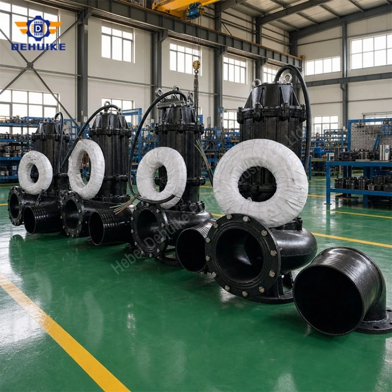
Wet-Well, Piping and Installation Engineering
Many blockage complaints attributed to a non-clogging submersible sewage pump actually begin outside the pump. A poorly shaped wet well can create stagnant corners, floating mats, sediment banks and air-entraining vortices. A discharge pipe that is too large may not carry settled material out of the station, while a pipe that is too small raises friction loss and shifts the pump away from the intended operating point. Pump, wet well and pipework must be evaluated as one hydraulic system.
How should the wet well be arranged?
Incoming flow should reach the pump intake without striking the unit directly or sweeping large debris into one side of the suction opening. The floor should limit dead zones and guide settled material toward the operating pump. Adequate spacing between multiple units helps prevent one pump from disturbing the inlet flow of another. The lowest stop level should still maintain the submergence required by the selected unit and installation arrangement.
How should the discharge line be sized?
The design engineer should calculate static lift, straight-pipe friction and losses from elbows, check valves, isolation valves, reducers and outlet fittings. The resulting system curve is compared with the pump curve. Pipe velocity must remain sufficient to transport expected solids, but the line should not be reduced merely to increase velocity because the added friction can consume the available head. A clean-out point or flushing connection can be included where long horizontal runs are unavoidable.
Which installation accessories matter?
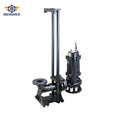
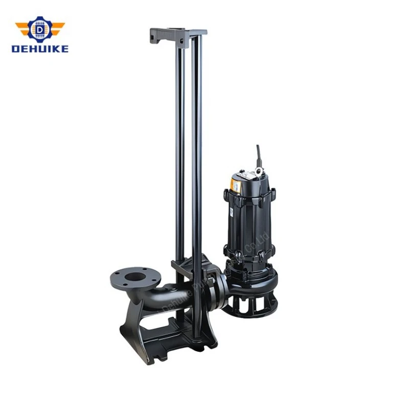
•Guide system: A guide arrangement permits vertical retrieval from the wet well while the fixed discharge connection remains in place. Rail alignment and lifting-chain position should prevent the unit from binding during removal.
•Discharge seat: The mating base must provide a stable seal under the pump's own weight and withstand piping reaction forces. Concrete anchors and grout should suit the equipment mass and the civil foundation.
•Check valve: A non-return valve limits reverse flow after shutdown. Its closing behavior should be considered where long rising mains could produce surge or repeated slam.
•Isolation valve: An isolation valve allows downstream service without draining the whole line. It should be accessible from a safe operating level.
•Lifting equipment: The chain, shackle and hoist must be rated for the installed pump mass, including fouling and water retained during lifting. The power cable must never be used as a lifting member.
A sound installation design reduces the number of variables that can be mistaken for a pump defect. It also creates safer access for inspection and preserves the anti-blocking advantage of the selected non-clogging submersible sewage pump.
Control, Alarm and Motor-Protection Logic
The electrical control philosophy determines how well a sewage station responds to changing inflow, blockage, abnormal temperature and seal deterioration. A non-clogging submersible sewage pump should be connected to a panel designed for the motor rating, starting method, sensor set and number of installed units. Generic motor starters that ignore embedded protection signals can allow a minor hydraulic problem to develop into a motor failure.
Level-based sequencing. Float switches, pressure transmitters or ultrasonic level sensors can command start, stop and high-level alarm points. In duplex or triplex stations, duty rotation equalizes running hours and keeps the standby unit proven. Peak inflow can call a second pump, provided the combined operating point is checked against the shared rising main.
Overload and phase supervision. The panel should monitor motor current, phase loss, phase imbalance and incorrect phase sequence. A sudden current rise can indicate a jammed impeller or obstructed discharge; a low current combined with poor output can indicate air entrainment, low liquid level or mechanical uncoupling.
Thermal protection. Embedded winding temperature devices provide a direct indication of motor heating. Alarm and trip thresholds must follow the motor documentation and must not be bypassed to keep the station running. The cause-frequent starts, overload, high liquid temperature, cooling loss or voltage imbalance-should be investigated before restart.
Leakage supervision. Where the selected configuration includes a seal-leak or moisture sensor, its circuit should produce an early maintenance alarm rather than wait for insulation failure. Trending the alarm together with oil-chamber observations helps maintenance staff plan intervention before secondary damage develops.
Variable-speed operation. A variable-frequency drive can help match inflow and limit abrupt hydraulic changes, but minimum speed must preserve adequate solids transport in the pump and pipe. The VFD should include appropriate motor protection, cable considerations and a bypass or contingency plan where uninterrupted service is critical.
Alarm history is valuable operating evidence. Repeated high-current trips at low wet-well level, frequent restarts after short run periods or leakage alarms after every cleaning event each point to a different root cause. A properly configured control system turns the non-clogging submersible sewage pump from a standalone machine into a measurable wastewater asset.
Energy Use and Operating-Point Management
Energy cost is governed by the entire pumping system, not motor nameplate power alone. The practical objective is to move the required wastewater volume through the actual system head with stable operation and limited recirculation. ISO/ASME 14414:2019 defines requirements for conducting and reporting pumping-system energy assessments, reinforcing the need to study the system rather than judge a pump by a single catalog efficiency value.
What shifts a pump away from efficient operation?
Changing wet-well levels alter static head. Partially closed valves, fouled rising mains and added fittings increase dynamic losses. Two pumps operating in parallel do not necessarily double flow because the shared system curve becomes steeper. Conversely, an oversized unit may empty the well too quickly, then cycle repeatedly. These conditions can raise energy per cubic meter even when the motor itself is functioning correctly.
Which operating data should be tracked?
Run hours and starts: A rising number of starts per day may indicate a narrow control band, an oversized pump or inflow instability.
Wet-well level trend: Level change during operation reveals whether delivered flow is keeping pace with incoming flow.
Motor current and power: Trend changes at similar levels can reveal fouling, wear, voltage conditions or a shifted hydraulic duty.
Delivered flow or drawdown test: Periodic flow confirmation prevents hidden capacity loss from being mistaken for normal seasonal variation.
Energy per transferred volume: kWh per cubic meter provides a more useful station benchmark than motor power by itself.
The WQ data used for this product family includes rated flows from 10 to 2,500 m³/h, rated heads from 7 to 41 m and motor ratings from 0.75 to 200 kW. That broad range allows the engineer to select a model around the real duty instead of forcing one motor size to serve every station. The preferred choice is the non-clogging submersible sewage pump that satisfies peak hydraulic demand while spending most annual running hours in a stable, efficient part of its curve.
Preventive Maintenance and Service Intervals
The purpose of preventive maintenance is to identify a developing problem while the pump is still available for planned removal. A non-clogging hydraulic reduces avoidable blockage, but it does not eliminate bearing wear, cable damage, seal aging, abrasive clearance growth or buildup caused by an unsuitable operating pattern. The maintenance plan should use condition evidence and service severity rather than a single calendar interval for every station.
Recommended inspection framework
Routine operating check: Confirm discharge behavior, current, abnormal vibration, unusual sound, alarm history and wet-well drawdown. Record observations so gradual change is visible.
Cable and lifting inspection: Check the visible cable jacket, gland area, chain, shackles and guide components. Replace damaged lifting hardware; never suspend the unit by its cable.
Oil-chamber review: During scheduled removal, inspect oil quantity and appearance in accordance with the pump manual. Water contamination or metallic debris requires investigation before return to service.
Impeller and volute examination: Remove wrapped fibers, inspect leading edges and confirm that wear has not enlarged hydraulic clearances enough to reduce output.
Fastener and seal review: Check external fasteners, O-rings and mating surfaces before reassembly. Use the specified gasket material and tightening sequence.
Electrical testing: Measure insulation resistance using procedures suited to the motor and sensors. Compare readings with prior values rather than relying on a single isolated measurement.
Severe grit, corrosive liquid, frequent starting or long idle periods may justify shorter intervals. A screened municipal station operating near design duty may allow longer intervals than a food-processing pit carrying fibrous by-products. Critical stations should keep a documented spare-parts list and a removal plan that identifies hoist capacity, isolation steps and safe work controls.
Maintenance records also support procurement decisions. If repeated service events show that fibers are wrapping at the inlet, a different hydraulic geometry or upstream screening strategy may be justified. If wear rather than wrapping dominates, materials and operating velocity deserve attention. This evidence-based approach protects the service life of the non-clogging submersible sewage pump while keeping maintenance expectations realistic and measurable.
Troubleshooting by Symptom and Evidence
Troubleshooting should begin with the observed symptom and measured evidence, not with immediate part replacement. The matrix below separates hydraulic, electrical and installation causes that can produce similar field behavior. Lockout, isolation and confined-space procedures must be followed before any physical inspection.
Because several causes can coexist, one corrective step should be verified before moving to the next. For example, clearing a blockage without correcting low transport velocity may restore the station only temporarily. Root-cause documentation turns each service call into better selection and operating knowledge for the next non-clogging submersible sewage pump project.
|
Observed symptom |
Likely checks |
Corrective direction |
|
Pump runs but wet-well level does not fall |
Discharge valve position, check-valve blockage, reverse rotation, air pocket, worn hydraulic parts, actual inflow |
Verify rotation and current, inspect discharge path, compare delivered flow with expected duty, then inspect impeller and volute. |
|
Repeated overload trip |
Solids jam, phase imbalance, low voltage, high head, bearing drag, incorrect protection setting |
Isolate power, clear obstruction safely, check supply and current by phase, confirm system head and mechanical freedom. |
|
Frequent clogging |
Debris type, pump passage, inlet layout, low pipe velocity, operation far from selected point |
Characterize the solids, review wet-well flow path and hydraulic selection, then consider screening or an alternative impeller arrangement. |
|
Excessive vibration or noise |
Loose guide components, cavitation-like inlet conditions, worn bearing, damaged impeller, trapped debris |
Inspect installation stability and intake conditions; retrieve the pump if condition persists. |
|
Low insulation resistance or leakage alarm |
Cable damage, gland damage, moisture ingress, seal-chamber condition |
Remove from service, perform qualified electrical testing and inspect sealing components before energizing. |
|
Too many starts per hour |
Control-band spacing, oversized pump, inflow pulses, failed level device, reverse flow |
Review level logic, check valve operation and station drawdown; resize or adjust control strategy where justified. |
Retrofit and Replacement Planning
Replacing an aging sewage pump is rarely a nameplate-only exercise. Existing stations may have changed since the original installation: additional buildings increase inflow, pipes acquire deposits, valves have been replaced and control levels may have shifted. A successful retrofit begins with a field survey that confirms the current duty, civil geometry and electrical conditions.
Hydraulic equivalence. Record measured drawdown, wet-well operating levels, discharge pressure where available and the existing pipe route. The replacement should be evaluated against the current system curve, not assumed to match because the nominal flow and head look similar.
Dimensional compatibility. Check the guide arrangement, discharge-seat centerline, rail spacing, lifting clearance, hatch dimensions and maximum lifting mass. An adapter may be preferable to civil reconstruction, but it must not introduce a restrictive passage or unstable load path.
Electrical compatibility. Confirm supply voltage, frequency, starting method, cable length, sensor wiring and panel capacity. Motor current, protection settings and starting demand must suit the existing feeder and generator, if present.
Duty resilience. Where the station has no redundancy, a duty/standby arrangement can reduce service risk. For parallel installations, the combined operating point and shared main must be recalculated before adding capacity.
Commissioning evidence. Record rotation, insulation condition, current by phase, start and stop levels, drawdown performance, alarm functions and leakage/thermal signal continuity. These values establish a baseline for later condition monitoring.
Retrofit planning is also an opportunity to solve historical blockage. Waste composition, maintenance notes and removed debris should be reviewed before confirming the new hydraulic configuration. A non-clogging submersible sewage pump selected from current evidence can improve operational consistency without requiring unsupported claims about universal interchangeability.
Accessories, Configuration and Verified Duty Data
|
Configuration item |
Purpose |
Selection note |
|
Auto-coupling discharge seat |
Provides a fixed wet-well discharge connection and retrieval interface |
Match outlet size, flange drilling and guide arrangement. |
|
Guide rails and upper bracket |
Keeps lifting path controlled |
Rail material and length should suit wet-well depth and environment. |
|
Certified lifting chain |
Allows retrieval from operating level |
Working load limit must exceed pump mass with suitable safety allowance. |
|
Check and isolation valves |
Controls reverse flow and isolates downstream piping |
Size for hydraulic loss, solids behavior and surge response. |
|
Level instruments |
Commands pump sequence and alarms |
Select float, pressure or ultrasonic technology for the well conditions. |
|
Control panel / VFD |
Provides starting, rotation, protection and monitoring |
Match motor current, sensors, power supply and station operating philosophy. |
|
Spare-parts set |
Supports planned maintenance and shorter outage |
Specify seals, O-rings, bearings and hydraulic wear items by exact model. |
Representative WQ rated-duty data
The following models are a new, non-repeated sample from the supplied WQ technical parameter workbook. Values are shown at the rated duty point. Model 50WQ24-20-14 appears exactly as printed in the source workbook; the same workbook records its motor rating as 4 kW and flags the printed model code for engineering confirmation before publication or quotation.
|
Model |
Out. mm |
Q m³/h |
H m |
kW |
r/min |
η % |
kg |
L×W×H mm |
|
50WQ10-10-0.75 |
50 |
10 |
10 |
0.75 |
2900 |
54 |
45 |
286×198×550 |
|
50WQ24-20-14* |
50 |
24 |
20 |
4 |
2900 |
69 |
130 |
520×400×740 |
|
65WQ25-15-2.2 |
65 |
25 |
15 |
2.2 |
2900 |
52 |
60 |
333×215×610 |
|
80WQ-50-25-7.5 |
80 |
50 |
25 |
7.5 |
2900 |
56 |
140 |
435×276×790 |
|
100WQ70-22-11 |
100 |
70 |
22 |
11 |
1450 |
70 |
260 |
560×410×970 |
|
150WQ140-7-5.5 |
150 |
140 |
7 |
5.5 |
1450 |
79 |
180 |
545×450×830 |
|
200WQ250-11-15 |
200 |
250 |
11 |
15 |
1450 |
73 |
350 |
620×380×1050 |
|
200WQ310-13-22 |
200 |
310 |
13 |
22 |
1450 |
71 |
450 |
930×600×1060 |
|
250WQ600-15-45 |
250 |
600 |
15 |
45 |
1450 |
73 |
950 |
1050×700×1650 |
|
300WQ480-15-45 |
300 |
480 |
15 |
45 |
1450 |
76 |
1500 |
1110×900×1770 |
|
350WQ1085-28-132 |
350 |
1085 |
28 |
132 |
980 |
83 |
2520 |
1520×1300×2500 |
|
400WQ1500-26-160 |
400 |
1500 |
26 |
160 |
980 |
82 |
2880 |
1650×1300×2500 |
|
500WQ2500-12-110 |
500 |
2500 |
12 |
110 |
980 |
85 |
2100 |
1580×1050×2200 |
Information needed for model selection
- Hydraulic duty: Required flow, total dynamic head, minimum and maximum wet-well levels, pipe length, diameter and major fittings.
- Wastewater description: Temperature, pH, density, expected solids size, fiber/rag content, grit concentration and any corrosive constituents.
- Electrical supply: Voltage, frequency, phase, allowable starting method, cable run and available panel protection.
- Installation scope: Fixed or guide-rail arrangement, wet-well depth, hatch size, lifting capacity and required valves or instruments.
- Operating philosophy: Duty/standby sequence, expected starts per hour, variable-speed requirement and alarm integration.
Providing these details allows the supplier to propose a duty-specific configuration rather than rely on a broad catalog label. The result is a non-clogging submersible sewage pump package aligned with the actual wet-well, solids profile and maintenance plan.
Hot Tags: non-clogging submersible sewage pump, China non-clogging submersible sewage pump manufacturers, suppliers, factory