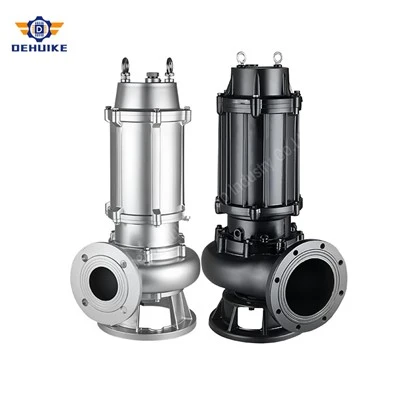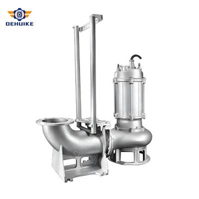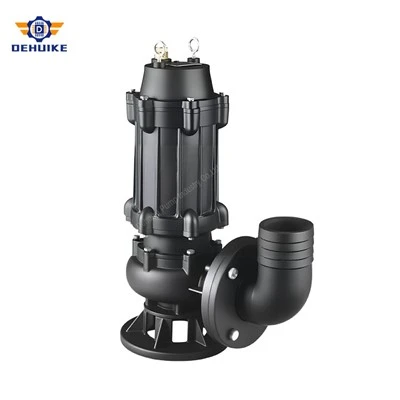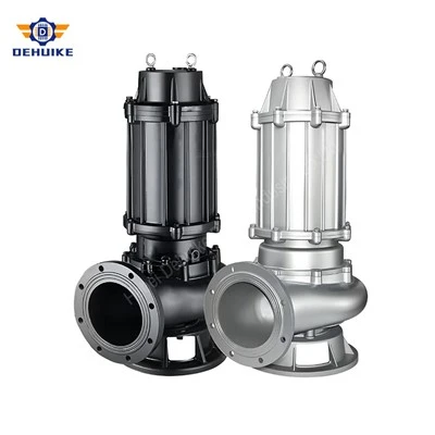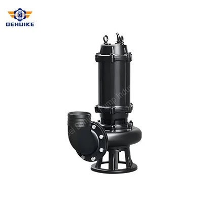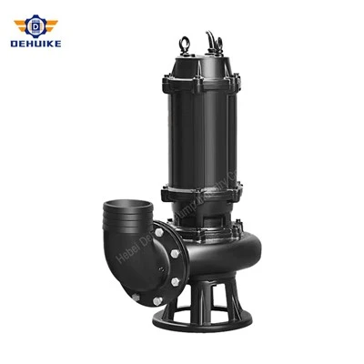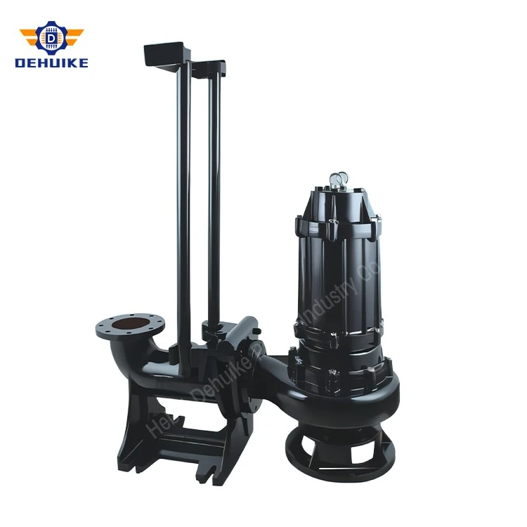
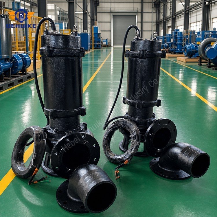
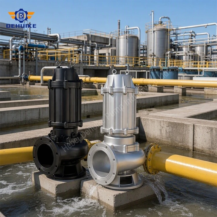
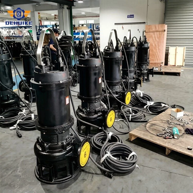
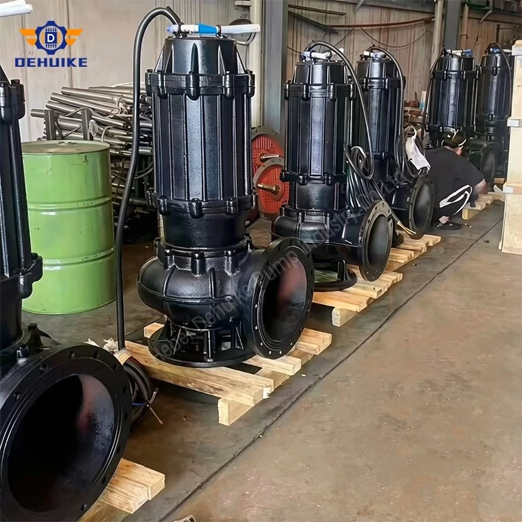
Hebei Dehuike Pump Industry Co., Ltd. is one of the most reliable manufacturers and suppliers of cutting submersible sewage pump in China. With abundant experience, we are committed to providing high quality customized pumps with competitive price. Welcome to wholesale bulk cutting submersible sewage pump for sale here from our factory. Also, pricelist is available.
What the Cutter Should and Should Not Process
A cutting submersible sewage pump combines wastewater transfer with a cutting or shearing stage near the inlet. Its purpose is to reduce flexible material that would otherwise wrap around the rotating assembly, bridge across a passage or accumulate in a discharge line. The cutter is not a general-purpose shredder, and responsible selection begins by defining which debris is expected, how often it enters the sump and what must remain outside the pump.
Soft fibers, cloth strands, plant material and similar flexible debris may respond to cutting when their size, toughness and feed rate suit the selected cutter. Dense metal objects, stones, thick rigid plastic, wire rope and hard construction waste are different hazards. They can chip cutting edges, jam the rotating group or damage the casing. A buyer should never interpret "cutting" as permission to remove upstream source control.
Describe shape, not only diameter. A long strip can wrap around a shaft even when its thickness is small. A compact soft solid of the same maximum dimension may pass without cutting. Photographs, sample bags and blockage records help define the real problem.
Separate continuous load from occasional debris. A cutter that handles an occasional rag may not be suitable for a continuous stream of textile waste. Daily mass, peak batch size and feeding pattern influence torque and wear.
Identify entrained hard contaminants. Sand, glass fragments, metal pieces and gravel can reach the cutting area together with fibers. These contaminants influence cutter material, clearances and the need for screens or traps.
Record grease and temperature. Fat can bind chopped material into a sticky mass, while hot or chemically aggressive liquid can affect seals, coatings and elastomers. The entire liquid condition must be specified.
Define prohibited objects. The operating manual and site procedure should state items that require upstream removal. Clear limits protect the pump, the operator and the wastewater system.
This debris profile becomes the functional specification for the cutting submersible sewage pump. Without it, a cutting claim cannot be evaluated and two quotations may describe very different capabilities under the same product title.
Cutting-Head Architecture and Feed Path
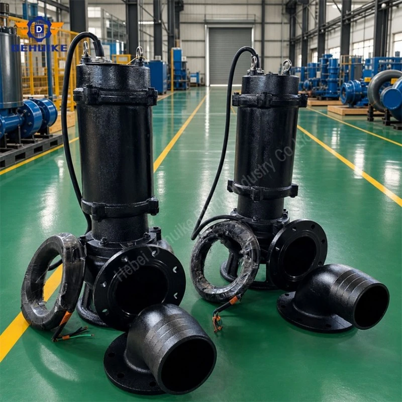
Cutting performance depends on how debris reaches the moving edge, how it is supported during shearing and where the reduced material travels after the cut. A cutter placed near the suction entrance can act before fibers enter the hydraulic passage, but its arrangement must preserve adequate inlet area and avoid creating a new restriction.
Rotating and stationary interaction. Many cutting concepts use a rotating edge working against a stationary element. Effective shearing requires controlled relative clearance and stable support. Excessive clearance may fold material rather than cut it; overly tight clearance may increase rubbing or sensitivity to grit.
Feed capture. The inlet should bring flexible debris into the cutting zone rather than let it circulate around the perimeter. Debris orientation is unpredictable, so the geometry must be assessed with representative material instead of ideal laboratory strands alone.
Discharge of reduced material. After cutting, fragments must pass through the impeller and rising main. A successful cut at the inlet does not help if fragments collect downstream because transport velocity is inadequate.
Protection from hard objects. The cutter should be considered together with upstream screening and sump housekeeping. A sacrificial or replaceable wear component may be preferable where occasional hard contamination cannot be eliminated.
Service access. Inspection should not require destructive disassembly. The maintenance plan should define how the cutting parts are exposed, measured, sharpened or replaced while preserving seal cleanliness and assembly alignment.
The supplied WQ workbook establishes hydraulic duty data but does not document cutter-blade count, cutting-edge material, clearance or validated cutting size. Those values must be stated on the model-specific quotation or technical data sheet before the unit is represented as a cutting configuration.
Hydraulic inlet performance also deserves attention. A cutting attachment occupies space in front of the suction opening and can influence approach velocity, local loss and the way air or debris enters the pump. The offered assembly should therefore be evaluated as a complete cutter-and-pump unit, not as a standard hydraulic curve with an unrelated accessory added later. If the cutter changes the certified duty, the supplier should provide the applicable curve or test evidence for the assembled configuration.
The direction of rotation is equally important. A cutting edge designed for one rotational direction may not function correctly after incorrect phase connection, even if liquid movement is still observed. Commissioning should confirm phase sequence and actual rotation using a safe method defined by the manufacturer before debris is introduced.
Torque Demand, Jamming and Motor Load
Cutting adds a transient mechanical load before the pump performs its hydraulic duty. A tough bundle entering the cutting zone can raise torque quickly, slow the rotating assembly and increase current. The selection must account for both steady hydraulic load and short-duration cutting events without treating motor power as unlimited reserve.
Which conditions increase cutting torque?
Tougher fibers: Reinforced textile, rope-like material and multilayer wipes can require more shearing effort than soft paper or plant fibers.
Larger batch entry: Several pieces entering together can produce a short torque peak even when each piece is individually manageable.
Worn edges: A rounded edge tends to drag or tear, increasing residence time and load compared with a serviceable edge.
Incorrect clearance: Clearance outside the intended range can reduce shearing effectiveness or create rubbing.
Hard inclusions: Metal, stone or rigid plastic can stop the cutter abruptly and should be treated as an abnormal event.
Current monitoring can reveal a developing restriction, but the protection scheme must distinguish an acceptable brief peak from a locked-rotor or repeated overload condition. Protection settings should follow the offered motor and control system; they should not be increased merely to prevent nuisance trips.
A duty review should include rated pump current, starting method, allowed starts per hour, cable length, voltage tolerance and expected cutting-event frequency. Where an anti-jam reversal sequence is proposed, its availability and limitations must be confirmed for the actual panel and pump configuration.
Anti-Stall Control and Safe Recovery
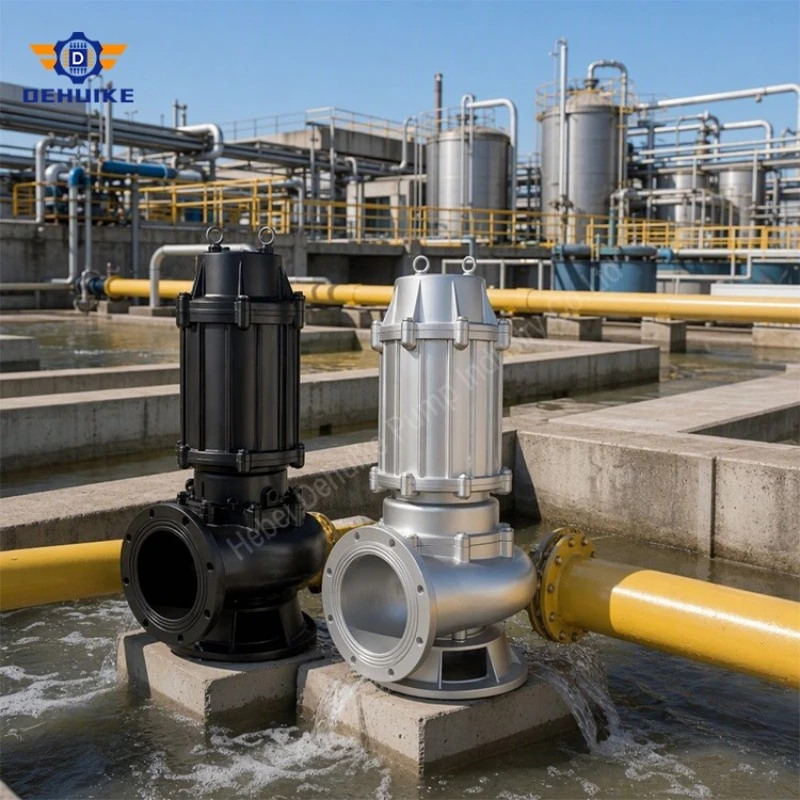
Control logic cannot make unsuitable debris cuttable, but it can limit damage and shorten response time when the rotating group slows or stops. A cutting submersible sewage pump should have a defined trip-and-recovery philosophy that protects personnel from unexpected restart and prevents repeated automatic attempts from worsening a jam.
Overcurrent recognition. The panel should detect abnormal current or overload using settings appropriate to the motor. Event records should identify which unit tripped and whether the alarm occurred during start, steady pumping or a cutting surge.
Limited restart attempts. Repeated automatic restarts can heat the motor and compact debris. If automatic retry is permitted, the number, delay and lockout condition should be documented.
Reverse or jog function. Some configurations may offer controlled reverse movement to release flexible material. This is not universal and should only be claimed when the motor, cutter, impeller, seals and controls are approved for that sequence.
Manual intervention boundary. Operators must isolate electrical and hydraulic energy before lifting or opening the pump. ISO 14118:2017 addresses designed-in measures for preventing unexpected machine start-up during human intervention.
Return-to-service check. After clearing a jam, inspect the cutter, fasteners, impeller, cable and seal area as applicable. Verify rotation, current, level logic and discharge response before automatic duty resumes.
The safe response procedure belongs in the station documentation and operator training. A cutting mechanism introduces accessible sharp edges during maintenance, so handling instructions and protective equipment should address both contamination and laceration hazards.
Cutter Wear and Functional Performance Verification
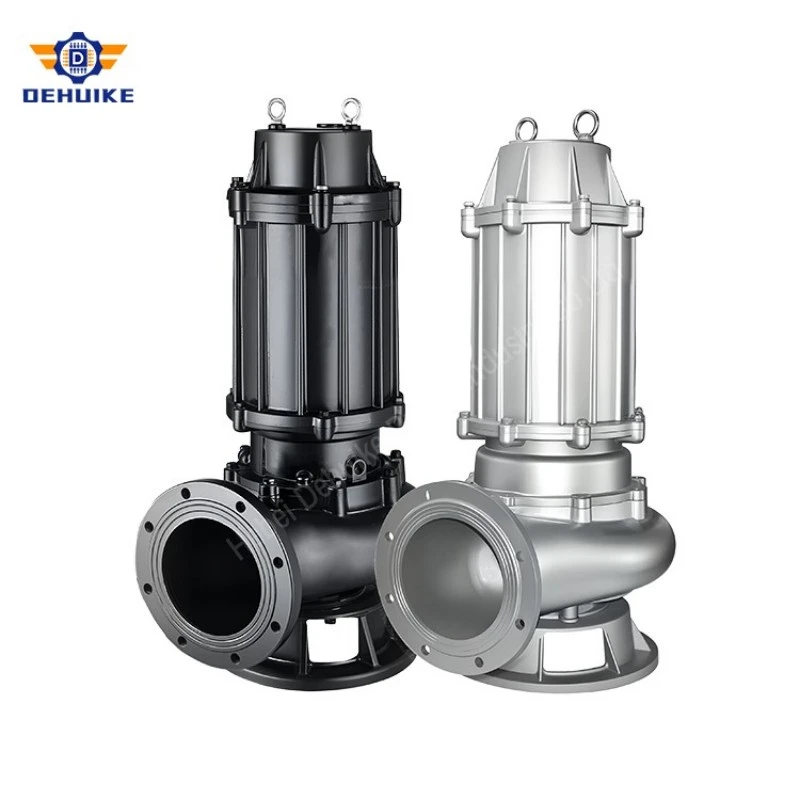
Cutter condition cannot be judged only by whether the motor still runs. Edge rounding, clearance growth, impact damage and corrosion can reduce cutting quality before hydraulic output changes visibly. Inspection should therefore include measurable cutter criteria alongside conventional pump checks.
Wear intervals depend on debris, grit, operating hours and cutter material. A fixed replacement calendar may be too long for abrasive duty and unnecessarily short for mild service. Condition records allow the site to establish a practical interval without promising a universal blade life.
|
Inspection item |
Evidence to record |
Service decision |
|
Edge condition |
Rounding, chips, corrosion, deformation and photographs |
Continue, sharpen if permitted, or replace with the specified part. |
|
Working clearance |
Measured value and method stated by the model documentation |
Adjust only within the approved range; investigate fastener or bearing movement. |
|
Fasteners and locking |
Torque condition, locking device and visible movement |
Replace damaged hardware and use the stated assembly method. |
|
Rotating freedom |
Manual check under safe isolation and evidence of rubbing |
Do not energize if hard contact or seizure is present. |
|
Functional sample |
Representative fiber sample and observed outcome |
Use for trend comparison; do not generalize beyond the tested material. |
|
Motor-load trend |
Current during comparable wet-well and flow conditions |
Investigate rising load together with cutter and hydraulic condition. |
Screening, Cutting and Downstream Transport
Cutting should complement wastewater management rather than replace it. Source control, coarse screening, grit removal, sump geometry, cutting action, pump passage and pipe transport all influence whether solids leave the station. Improving one stage while ignoring the next can simply move the blockage downstream.
Source control. Facilities should prevent metal, wire, stones, thick plastic and process scrap from entering the wastewater system where practicable. This reduces damage risk for every downstream asset.
Screen opening. A coarse screen can protect the cutter from oversized hard objects, but excessive restriction can raise upstream level and require frequent cleaning. Screen selection follows the site debris load and maintenance resources.
Grit separation. Mineral grit may not be cut and can abrade both cutter and hydraulic surfaces. Settling or separation may be more effective than relying on the pump to pass every particle.
Wet-well mixing. A cutter cannot process debris that remains trapped in a corner or floating mat. Inlet direction and level range should bring material toward the operating unit without creating air ingestion.
Rising-main velocity. Reduced fibers still need transport. Pipe diameter, flow, operating sequence and long horizontal sections should be reviewed for settling and re-entanglement risk.
A project review should map the solids path from process or sewer inlet to final discharge. The cutting submersible sewage pump is one engineered control point in that path, not a standalone answer to poor waste segregation.
Representative Debris Testing and Acceptance
A hydraulic test verifies flow and head under controlled liquid conditions; it does not automatically prove cutting performance on the buyer's debris. ISO 9906:2012 covers hydraulic performance acceptance testing for rotodynamic pumps with liquids behaving as clean, cold water. A cutting application may therefore need two separate evidence tracks: hydraulic acceptance and a project-specific functional cutting demonstration.
How should a functional test be planned?
- Sample definition: Use a documented sample that represents the expected fiber type, dimensions, moisture condition and batch quantity. Avoid vague descriptions such as "cloth" without photographs or specification.
- Safe test method: Define containment, guarding, isolation and collection of discharged material. Personnel must not hand-feed material into an exposed rotating cutter.
- Pass criteria: State whether acceptance concerns successful intake, absence of persistent jam, fragment condition, current behavior or repeatability. Criteria should be agreed before the test.
- Test limits: A passed sample does not prove performance on wire, metal, stone or untested reinforced material. The test report should state exclusions.
- Post-test inspection: Inspect cutting edges, fasteners and rotating freedom after the planned cycles to identify hidden impact or abnormal wear.
Video can support the report but should not replace recorded sample information, motor current, test sequence and inspection result. The resulting evidence gives the buyer a clearer basis than an unlimited cutting claim.
Repeatability matters more than a single successful event. Where the application is critical, the agreed test can use several controlled cycles and compare current response, processing time and cutter condition from the first cycle to the last. If performance deteriorates quickly, the result may indicate edge damage, unsuitable clearance or a sample load outside the intended duty.
The final report should identify the tested pump and cutter assembly, sample description, test date, electrical supply and observers. Any deviation from the agreed method should be recorded. This creates a usable procurement record instead of a promotional demonstration with unknown conditions.
Cutting Configuration Declaration and WQ Rated Data
The quotation for a cutting submersible sewage pump should declare which values come from verified WQ hydraulic data and which belong to the added cutting configuration. This prevents a standard WQ duty table from being misread as proof of cutter performance.
|
Quotation field |
What should be stated |
Evidence basis |
|
Hydraulic model |
WQ model, rated flow, head, speed, efficiency and motor power |
Supplied WQ workbook and approved pump curve. |
|
Cutting mechanism |
General arrangement and rotating/stationary cutting concept |
Model-specific drawing or data sheet. |
|
Cutting parts |
Material, part numbers and replaceability |
Supplier bill of materials and spare-parts list. |
|
Functional limit |
Accepted debris description and prohibited objects |
Agreed sample test or documented application statement. |
|
Control response |
Overload, retry, reversal if applicable, and lockout behavior |
Control schematic and panel settings. |
|
Maintenance requirement |
Inspection access, clearance check and service method |
Operation and maintenance manual. |
Sixth non-repeated sample of WQ rated-duty models
The following figures are copied from the supplied WQ workbook at the rated operating point. They can support hydraulic screening of a cutting-pump enquiry, but cutter availability and mechanical compatibility must be confirmed for the exact model before publication or quotation.
|
Model |
Out. mm |
Q m³/h |
H m |
kW |
r/min |
η % |
kg |
L×W×H mm |
|
50WQ18-15-1.5 |
50 |
18 |
15 |
1.5 |
2900 |
62 |
60 |
295×228×610 |
|
50WQ40-15-4 |
50 |
40 |
15 |
4 |
2900 |
67 |
130 |
520×394×750 |
|
80WQ43-13-3 |
80 |
43 |
13 |
3 |
2900 |
65 |
80 |
390×260×600 |
|
100WQ65-15-5.5 |
100 |
65 |
15 |
5.5 |
1450 |
59 |
150 |
545×360×850 |
|
100WQ87-28-15 |
100 |
87 |
28 |
15 |
1450 |
69 |
300 |
560×410×970 |
|
100WQ110-10-5.5 |
100 |
110 |
10 |
5.5 |
1450 |
67 |
150 |
545×370×850 |
|
150WQ140-41-37 |
150 |
140 |
41 |
37 |
1450 |
63 |
1150 |
895×720×1800 |
|
150WQ160-15-15 |
150 |
160 |
15 |
15 |
1450 |
67 |
300 |
710×455×900 |
|
150WQ250-22-30 |
150 |
250 |
22 |
30 |
1450 |
73.5 |
820 |
795×600×1200 |
|
200WQ300-7-11 |
200 |
300 |
7 |
11 |
1450 |
75 |
370 |
640×400×1050 |
|
200WQ400-7-15 |
200 |
400 |
7 |
15 |
1450 |
82 |
300 |
815×630×1120 |
|
250WQ700-11-37 |
250 |
700 |
11 |
37 |
1450 |
83 |
1150 |
980×680×1860 |
|
300WQ900-8-30 |
300 |
900 |
8 |
30 |
980 |
84.5 |
1150 |
1000×680×1860 |
For a model-specific proposal, provide required flow and head, pipe details, fiber type, sample photographs, batch frequency, hard contaminants, grit, temperature, chemistry, installation method, voltage, control requirements and desired functional test. Contact Hebei Dehuike Pump Industry Co., Ltd. at director@dhkpump.com or +86 19503223662 for engineering review.
Hot Tags: cutting submersible sewage pump, China cutting submersible sewage pump manufacturers, suppliers, factory