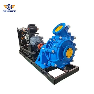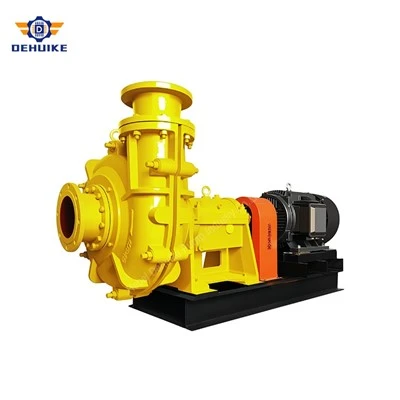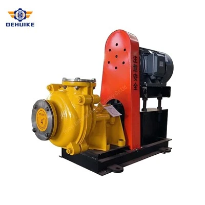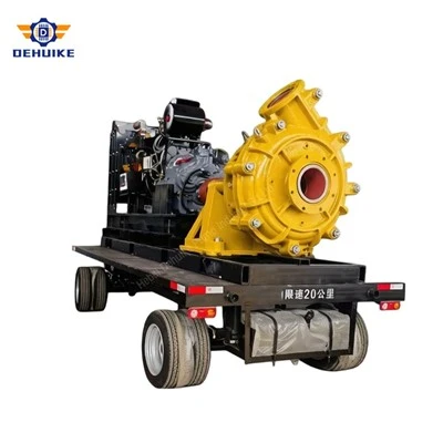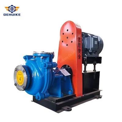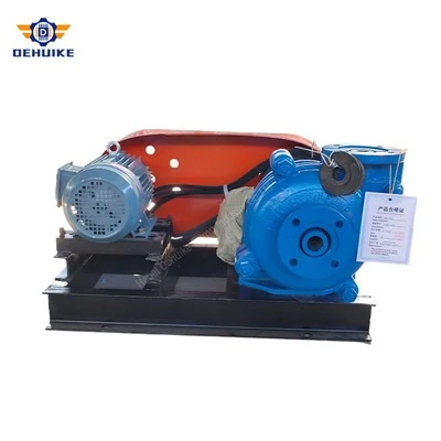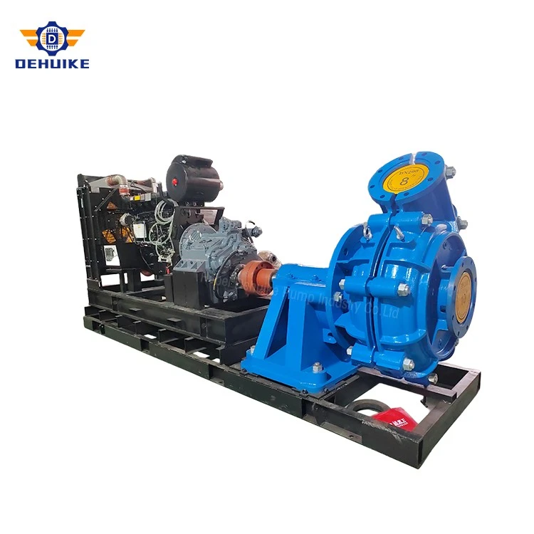
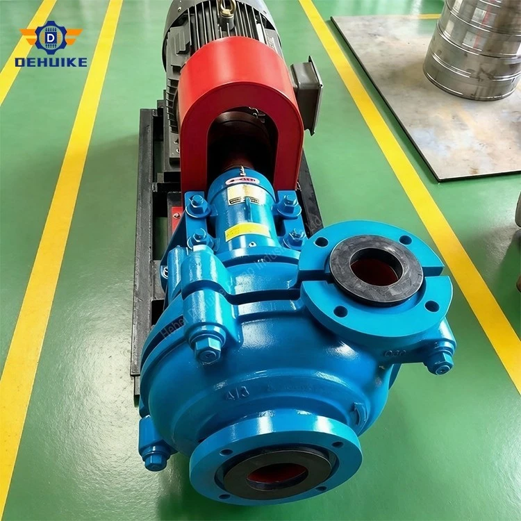
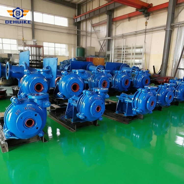
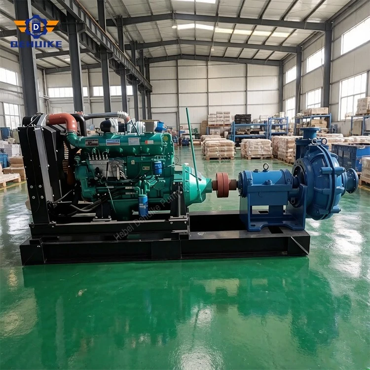
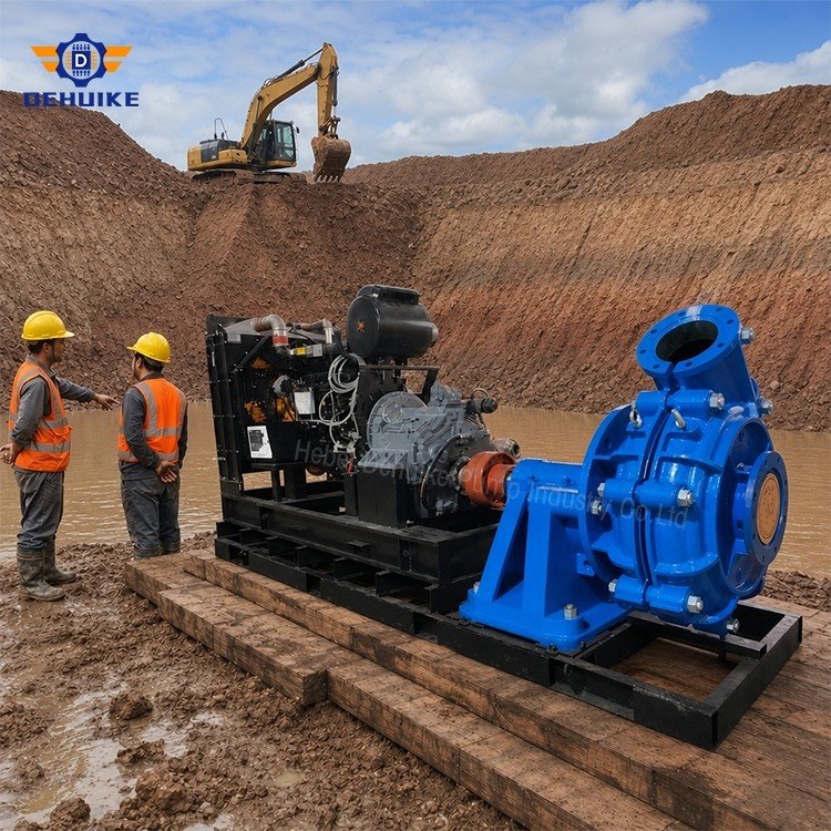
Hebei Dehuike Pump Industry Co., Ltd. is one of the most reliable manufacturers and suppliers of horizontal slurry handling pump in China. With abundant experience, we are committed to providing high quality customized pumps with competitive price. Welcome to wholesale bulk horizontal slurry handling pump for sale here from our factory. Also, pricelist is available.
Product Overview
Horizontal Slurry Handling Pump for Practical Plant Layouts
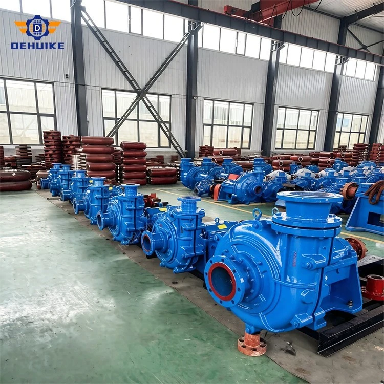
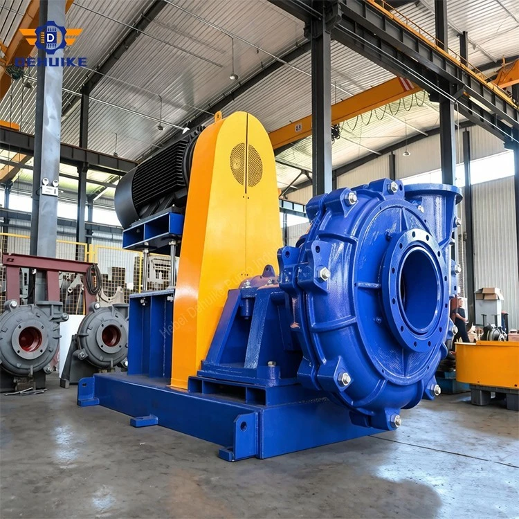
A Horizontal Slurry Handling Pump is arranged with its rotating assembly and hydraulic casing on a horizontal centerline, normally supported by a base, frame or skid. This layout is useful where the plant has a defined suction and discharge route, accessible floor space and a maintenance plan that requires convenient access to the coupling, bearing housing, seal area and wet-end components.
The pump is designed to move liquid containing suspended or settled solids between process points. The medium may contain sand, mineral fines, ash, residue, sludge or other particles that change the density and flow behavior of the liquid. A Horizontal Slurry Handling Pump should therefore be selected from the complete system duty, not from the pump orientation alone. Flow, total head, particle size, solids concentration, temperature, suction level and pipeline arrangement all affect the final configuration.
Horizontal installation can simplify connection to a floor-mounted drive and a conventional pipeline. It may also support easier inspection when the pump is installed with sufficient clearance and suitable lifting access. The actual access method depends on the ordered design, casing arrangement, drive package and site layout. This product-family draft is intended for engineering buyers, plant operators, project contractors, distributors and maintenance teams. Model-specific values must be completed from the approved curve, drawing, nameplate and current manual.
Horizontal Arrangement and Site Fit
Base and support
A horizontal pump should be installed on a foundation capable of carrying the pump, drive and operating loads. The base must be level enough for correct alignment, and the support should limit movement caused by vibration or pipe forces. The final foundation, anchor and grouting requirements must follow the supplied drawing.
Maintenance clearance
The site layout should leave room for coupling inspection, seal adjustment, bearing service, casing access and removal of major wear parts. A compact installation may save floor area but can increase maintenance time if lifting routes and working space are ignored during planning.
Lifting and replacement access
Before the pump is fixed in position, confirm how the motor, coupling, casing, impeller and liners will be moved during maintenance. The lifting point and handling method should be suitable for the actual ordered equipment. Do not assume that a general workshop lifting arrangement will fit every pump station.
Material Handling Route
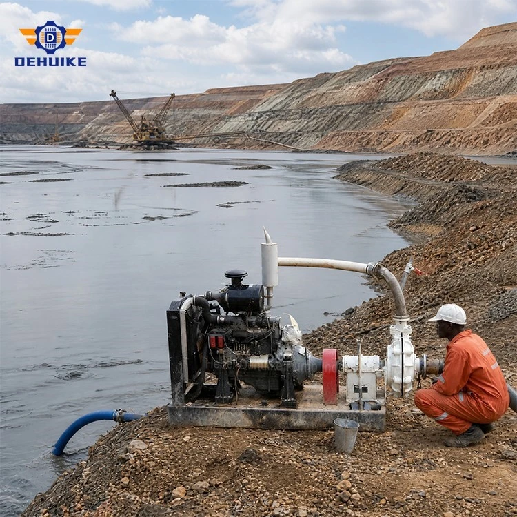
A Horizontal Slurry Handling Pump works as one part of a material route that may include a feed tank, suction pipe, pump, discharge line, valve group and receiving equipment. Each section should be reviewed together. A pump can be correctly sized for a stated flow and still perform poorly if the suction line allows air entry, the discharge line creates excessive resistance or the receiving vessel operates at a different pressure than expected.
Feed condition
Confirm whether the source is flooded, intermittently filled, open to atmosphere or connected to another pressurized process. Record the normal and minimum liquid levels. If solids settle near the suction entrance, the tank shape, agitation and restart procedure should be reviewed before the pump is selected.
Discharge destination
The receiving point may be a storage tank, filter, separation unit, dewatering device or another process vessel. Its required pressure and flow stability can affect the operating point. Include static elevation, pipe length, internal diameter, bends, valves and equipment losses in the system calculation.
Technical Specifications/Model number
|
Parameter |
Listing value |
|
Pump type |
Abrasion-Resistant Horizontal Centrifugal Slurry Pump |
|
Model |
DAH Series |
|
Construction |
Horizontal, single-stage, single-suction, cantilever design |
|
Capacity |
Up to 5,400 m³/h |
|
Head |
Up to 120 m |
|
Speed |
370–3,500 r/min |
|
Size range reference |
25–500 mm |
|
Temperature reference |
1–90°C |
|
Casing |
Ductile iron |
|
Impeller |
High-chrome white iron; optional elastomer configuration |
|
Liner |
High-chrome white iron or elastomer |
|
Seal |
Gland packing; expeller or mechanical seal by configuration |
|
Drive |
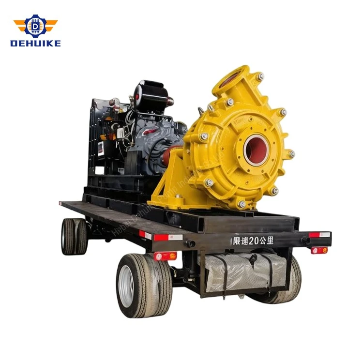
Electric motor or diesel drive, subject to project requirements |
|
Customization |
Flow, head, speed, motor power, voltage, frequency, seal, material and spare parts |
|
MODEL |
Maximum |
Material |
Fresh Water Performance |
Curve |
||||||||
|
Sheath |
Impeller |
Flow Q |
Flow Q |
LIFT |
Rotation |
Maximum |
Corrosion |
Blade |
Impellers |
|||
|
6/4D-HH |
60 |
M |
M |
162~360 |
45~100 |
12~56 |
800~1550 |
65 |
5~8 |
5 |
365 |
WPA64A01 |
|
6/4E-DAH |
120 |
M |
M |
162~360 |
45~100 |
12~56 |
800~1550 |
65 |
5~8 |
5 |
365 |
WPA64A01 |
|
6/4D-DAH |
60 |
M |
M |
180~396 |
50~110 |
7~6 |
600~1600 |
55 |
3~8 |
4 |
372 |
WPA64A02 |
|
6/4E-DAH |
120 |
M |
M |
180~396 |
50~110 |
7~6 |
600~1600 |
55 |
3~8 |
4 |
372 |
WPA64F02 |
|
6/4D-DAH |
60 |
RU |
RU |
144~324 |
40~90 |
12~45 |
800~1350 |
65 |
3~5 |
5 |
365 |
WPA64A03A |
|
6/4E-DAH |
120 |
RU |
RU |
144~324 |
40~90 |
12~45 |
800~1350 |
65 |
3~5 |
5 |
365 |
WPA64A03A |
|
6/4D-DAH |
60 |
M |
M |
144~324 |
40~90 |
10~52 |
800~1600 |
55 |
4.5~9 |
2 |
371 |
WPA64A04 |
|
6/4E-DAH |
120 |
M |
M |
144~324 |
40~90 |
10~52 |
800~1600 |
55 |
4.5~9 |
2 |
371 |
WPA64A04 |
|
6/4D-DAH |
60 |
M |
M |
162~360 |
45~100 |
21~64 |
1000~1600 |
55 |
2 |
371 |
ESY7996 |
|
|
6/4E-DAH |
120 |
M |
M |
162~360 |
45~100 |
21~64 |
1000~1600 |
55 |
2 |
371 |
ESY7996 |
|
|
6/4D-DAH |
60 |
M |
M |
126~288 |
35~80 |
10~55 |
800~1600 |
58 |
2~2.5 |
2 |
365 |
ESY7997 |
|
6/4E-DAH |
120 |
M |
M |
126~288 |
35~80 |
10~55 |
800~1600 |
58 |
2~2.5 |
2 |
365 |
ESY7997 |
|
6/4S-HH |
560 |
M |
M |
324~720 |
90~200 |
30~118 |
600~1000 |
64 |
3~8 |
5 |
711 |
WPA64BDLM |
|
6S-H |
560 |
M |
M |
468~1008 |
30~280 |
20~94 |
500~1000 |
65 |
4~12 |
5 |
711 |
WPA66A9I |
|
8/6E-DAH |
120 |
M |
M |
360~828 |
100~230 |
10~61 |
500~1140 |
72 |
2~9 |
5 |
510 |
WPA86A0 |
|
8/6R-DAH |
300 |
M |
M |
360~828 |
100~230 |
10~61 |
500~1140 |
72 |
2~9 |
5 |
510 |
WPA86A0 |
|
MODEL |
Maximum |
Material |
Fresh Water Performance |
Curve |
||||||||
|
Sheath |
Impeller |
Flow Q |
Flow Q |
LIFT |
Rotation |
Maximum |
Corrosion |
Blade |
Impellers |
|||
|
8/6E-DAH |
120 |
M |
M |
324~720 |
90~200 |
7~49 |
400~1000 |
65 |
5~10 |
5 |
510 |
WPA86A01B |
|
8/6R-DAH |
300 |
M |
M |
324~720 |
90~200 |
7~49 |
400~1000 |
65 |
5~10 |
5 |
510 |
WPA86A01B |
|
8/6E-DAH |
120 |
M |
M |
360~828 |
100~230 |
7~70 |
400~1140 |
70 |
3~6 |
8 |
536 |
WPA86A02 |
|
8/6R-DAH |
300 |
M |
M |
360~828 |
100~230 |
7~70 |
400~1140 |
70 |
3~6 |
8 |
536 |
WPA86A02 |
|
8/6E-DAH |
120 |
RU |
RU |
360~828 |
100~230 |
7~52 |
400~1000 |
70 |
2.5~6 |
4 |
536 |
WPA86A03 |
|
8/6R-DAH |
300 |
RU |
RU |
360~828 |
100~230 |
7~52 |
400~1000 |
70 |
2.5~6 |
4 |
536 |
WPA86F03 |
|
8/6E-DAH |
120 |
M |
M |
288~648 |
80~180 |
5~47 |
400~1100 |
60 |
3~6 |
2 |
510 |
ESY7998 |
|
8/6R-DAH |
300 |
M |
M |
288~648 |
80~180 |
5~47 |
400~1100 |
60 |
3~6 |
2 |
510 |
ESY7998 |
|
8/6T-HH |
1200 |
M |
M |
576~1152 |
160~320 |
32~95 |
450~725 |
65 |
6~10 |
5 |
965 |
WPA86E0 |
|
10/8E-M |
120 |
M |
M |
540~1228 |
150~340 |
15~61 |
600~1100 |
70 |
4.5~8 |
4 |
549 |
WPA108B0 |
|
10/8R-M |
300 |
M |
M |
540~1228 |
150~340 |
15~61 |
600~1100 |
70 |
4.5~8 |
4 |
549 |
WPA108B0 |
|
10/8E-M |
120 |
M |
M |
504~108 |
140~300 |
18~66 |
700~1100 |
62 |
4.5~7.5 |
4 |
549 |
WPA108B02 |
|
10/8R-M |
300 |
M |
M |
504~108 |
140~300 |
18~66 |
700~1100 |
62 |
4.5~7.5 |
4 |
549 |
WPA108B02 |
|
10/8E-M |
120 |
M |
M |
666~144 |
185~400 |
14~60 |
600~1100 |
73 |
4~10 |
5 |
549 |
WPA108B03 |
|
10/8R-M |
300 |
M |
M |
666~144 |
185~400 |
14~60 |
600~1100 |
73 |
4~10 |
5 |
549 |
WPA108B03 |
|
10/8E-M |
120 |
RU |
RU |
540~1188 |
150~330 |
10~42 |
500~900 |
79 |
5~9 |
5 |
549 |
WPA108B0SA |
|
10/8R-M |
300 |
RU |
RU |
540~1188 |
150~330 |
10~42 |
500~900 |
79 |
5~9 |
5 |
549 |
WPA108B0SA |
Main Components and Handling Function
Hydraulic casing
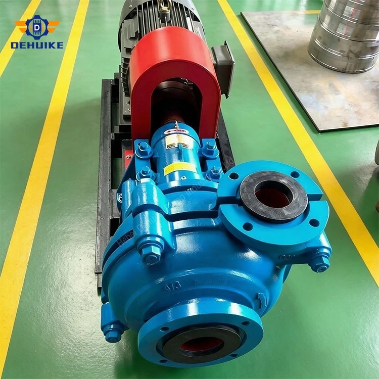
The casing receives the flow from the impeller and directs it toward the discharge nozzle. Its internal shape affects pressure recovery, flow direction and access to the wet-end assembly. The casing must be considered together with the selected impeller and wear components.
Impeller
The impeller adds energy to the slurry and influences capacity, head, power and particle movement. Its diameter, speed, passage and material must match the model design. A change in impeller size should not be made without checking the curve and motor load.
Bearing housing and shaft
The bearing housing supports the rotating shaft, while the shaft transfers torque from the drive to the impeller. Correct alignment, lubrication and bearing temperature control are important for stable horizontal operation.
Seal area
The shaft seal limits leakage around the rotating shaft. Packing, mechanical seals and flushing arrangements have different operating requirements. Seal water quality, pressure and flow should follow the selected configuration.
Operating Principle and Process Control
During operation, the pump should remain within the approved hydraulic range. Excessive throttling, air entry, dry running, low liquid level and frequent operation far from the design point may cause unstable pressure, seal stress, vibration, increased power demand or accelerated wear. If the process requires variable flow, confirm the control method and operating limits before commissioning.

Applications by Plant Function
- Feed transfer: moving slurry from a preparation tank to a processing unit.
- Sump recovery: lifting solids-bearing liquid from a low point to the main process route.
- Return circulation : returning process media to a previous stage for reuse or further treatment.
- Residue collection: moving residue from a collection point to storage or dewatering.
- Plant drainage transfer : handling selected solids-bearing drainage streams within confirmed limits.
- Pipeline elevation service: overcoming static lift and friction in a horizontal or mixed-elevation route.
- Temporary process routing: supporting an alternate line during maintenance or process adjustment, subject to duty verification.
Installation, Alignment and Commissioning
Check the foundation, anchor points and maintenance clearance before lifting the pump into position.
Level the base and complete alignment between the pump and drive.
Support suction and discharge piping independently so that pipe loads do not distort the casing.
Confirm that the suction line has no unintended air pocket, sharp restriction or sediment trap.
Check coupling guard, lubrication, seal connections and motor protection.
Verify rotation direction before the first loaded start.
Record flow, pressure, current, vibration, bearing temperature and leakage during commissioning.
Stop the equipment for investigation when abnormal noise, unstable pressure, overheating or leakage occurs.
Maintenance and Field Troubleshooting
A planned inspection should cover the impeller, casing, liner or wear surfaces, shaft seal, bearings, coupling, fasteners and pipe connections. Compare field readings with the original commissioning record. A lower flow at the same speed may indicate wear, blockage or increased system resistance. High current may relate to slurry density, excessive flow, mechanical friction or a changed operating point. Leakage may result from seal wear, incorrect flushing, shaft movement or damaged surfaces.
Before dismantling, record the actual condition, isolate the power, relieve pressure and drain the relevant section. Replacement parts must match the model, dimensions, material and drawing reference. A field repair should not introduce a different clearance, seal type or material without technical review.
Spare Parts and Lifecycle Planning
Keep a record of model numbers, material codes, drawing references, installation dates and replacement reasons. This information supports future maintenance decisions and helps distinguish normal wear from an incorrect operating condition.
Quality, Packing and Project Documents
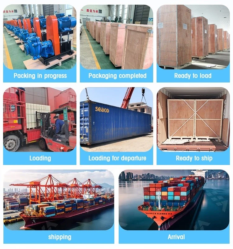
Packing should protect the pump and accessories from impact, dust and moisture during the agreed storage and transport conditions. The pump, drive components, accessories and spare parts should be separated and identified in the packing list where required. Project documents may include an approved drawing, operating notes, installation guidance, inspection record and spare-parts list when included in the supply scope.
FAQ
Q: Why choose a horizontal arrangement?
A: It may suit floor-mounted drives, conventional pipeline routes and sites that require accessible coupling, bearing and wet-end service. The final layout depends on the foundation, lifting route and maintenance space.
Q: What does the pump handle?
A: It may transfer liquid containing sand, mineral fines, ash, residue, sludge or other solids when the selected model and materials match the medium.
Q: What information is needed for selection?
A: Provide flow, total head, source and destination, pipe layout, particle size, solids concentration, specific gravity, temperature, chemistry, suction level and operating schedule.
Q: Can the pump work with a long discharge line?
A: It may be suitable when the pump curve, motor power and system resistance are reviewed together. Long lines, elevation changes and fittings must be included in the calculation.
Q: What can cause low flow?
A: Possible causes include suction restriction, air entry, blockage, excessive wear, an incorrect valve position, a changed system route or operation away from the approved point.
Q: How should the pump be restarted after a long shutdown?
A: Check liquid level, sediment, suction condition, seal arrangement, free shaft rotation and flushing requirements before restarting. Follow the model-specific procedure.
Q: Which spare parts are normally planned?
A: The plan may include wear components, seals, bearings, gaskets and coupling parts. The final list should follow the model, material, operating hours and inspection history.

Hot Tags: horizontal slurry handling pump, China horizontal slurry handling pump manufacturers, suppliers, factory