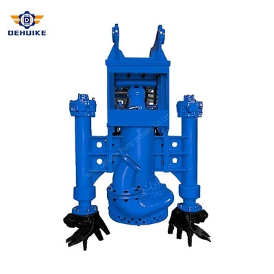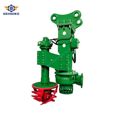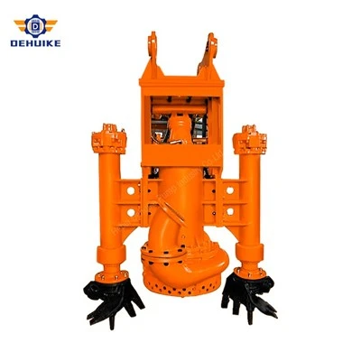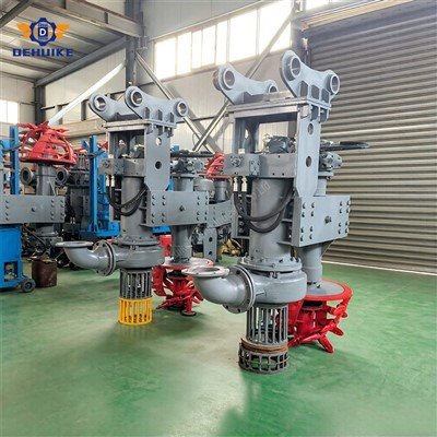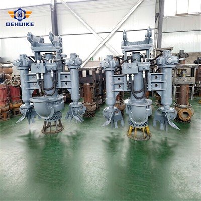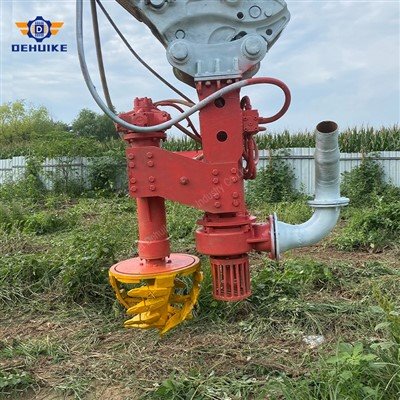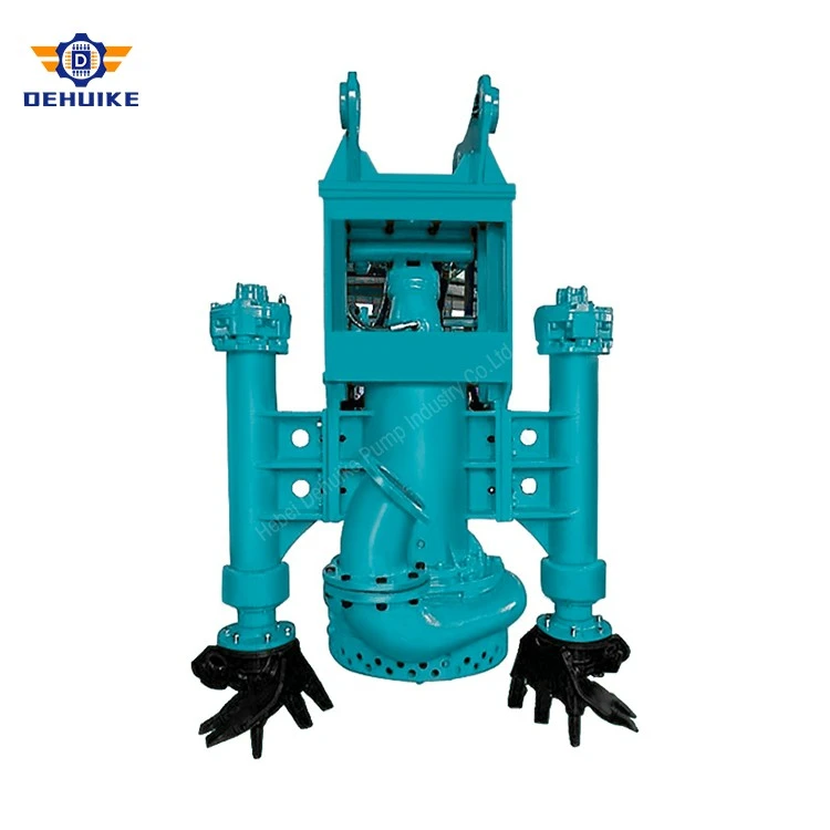
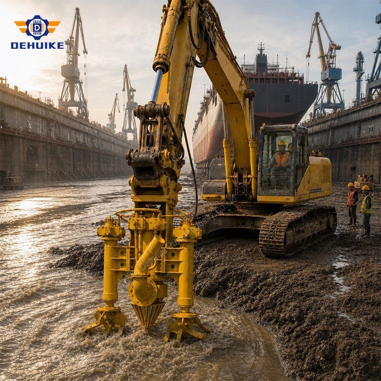
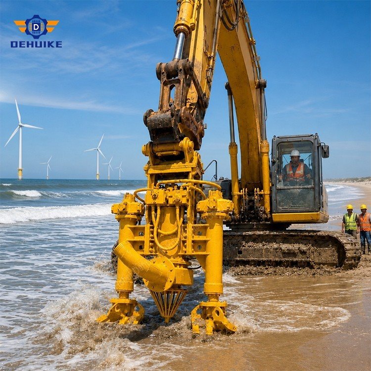
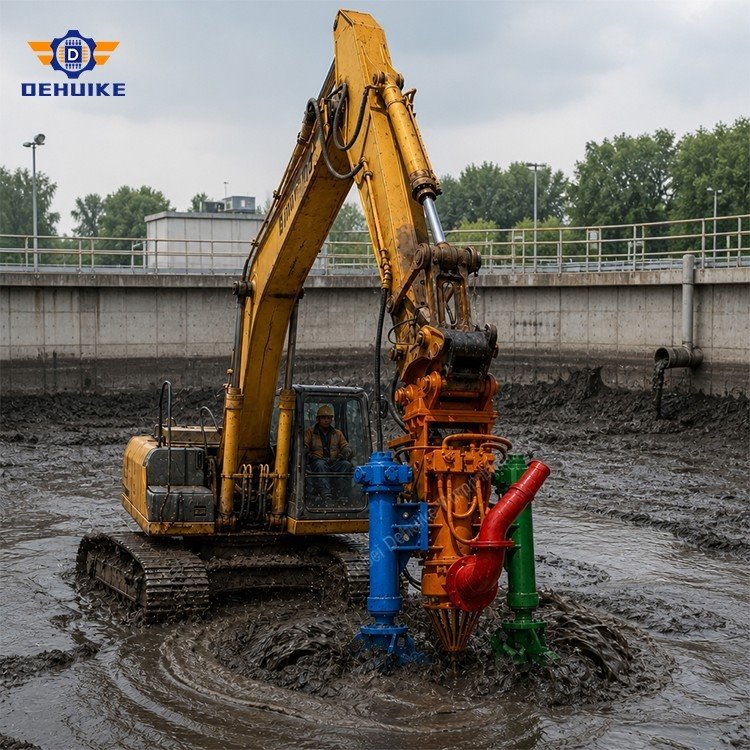
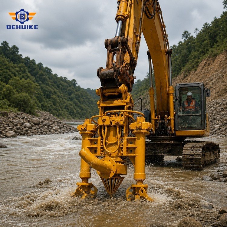
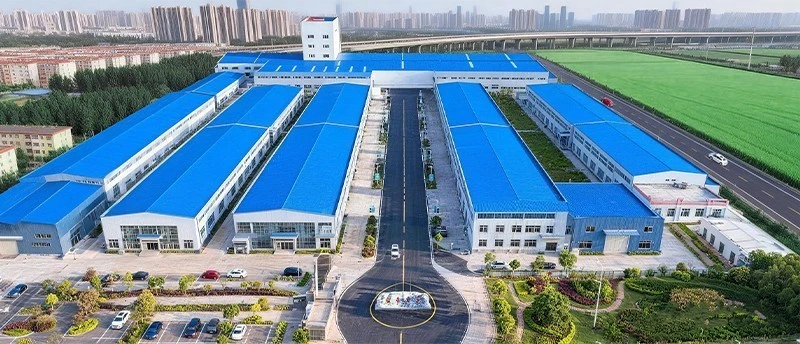
Hebei Dehuike Pump Industry Co., Ltd. is one of the most reliable manufacturers and suppliers of hydraulic sludge transfer pump in China. With abundant experience, we are committed to providing high quality customized pumps with competitive price. Welcome to wholesale bulk hydraulic sludge transfer pump for sale here from our factory. Also, pricelist is available.
The bend that ends a shift
A dredge crew in a gravel pit was running a hydraulic pump at about 200 m³/h through 150 mm hose. Production was steady until they added two 45° bends to route the discharge over a spoil wall. Two hours later the line started surging, then stopped. The crew pulled the pump, found a worn impeller, and ordered a bigger one.
The impeller was worn, but it was not the problem. The extra bends had cut velocity below the point where coarse sand stays suspended. Sand settled into a dune at the second bend and the pump was left pushing against its own spoil.
The short version
The model code carries the duty: the first number is nominal flow in m³/h, the second is head in metres, all at 1,450 rpm.
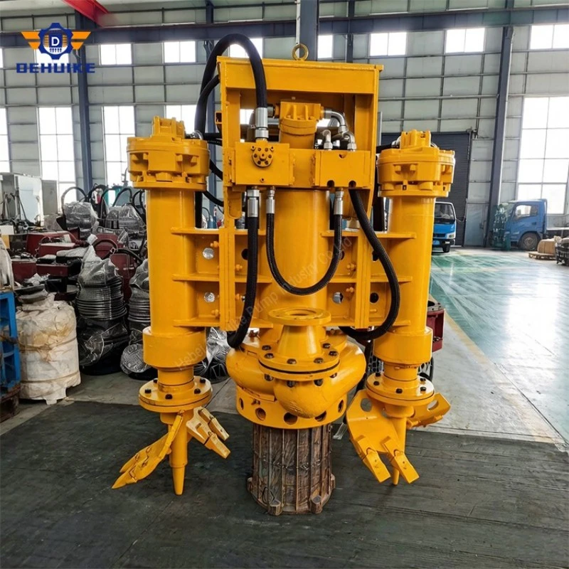
Hydraulic drive removes the electrics from the water and lets you dial speed and torque, but it adds a power pack, an oil cooling duty and a return-line pressure problem.
Published head and flow are water calibrations. Sand at 1.25 to 1.4 specific gravity changes both, so selection belongs on a slurry curve, not on the catalogue row.
Line velocity for coarse sand and gravel should stay around 2.5 to 3.2 m/s. Below it, dunes form; above it, wear climbs quickly.
Wear parts, not the pump, set the operating cost. Reading the wear pattern tells you whether the problem is velocity, air or alignment.
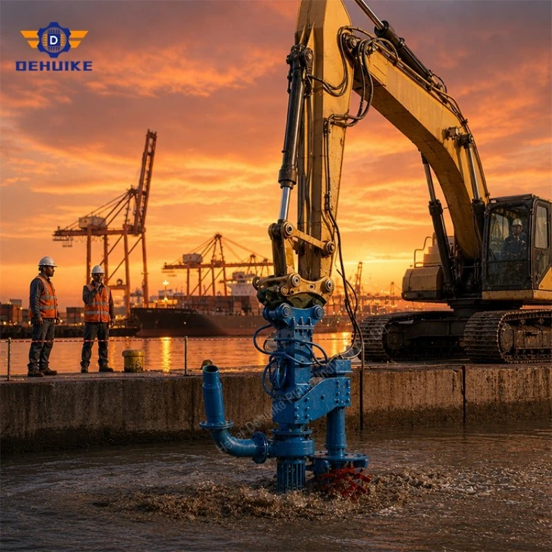
Reading the model code
The WJY range names itself after its duty point. WJY150-25 is a 150 m³/h, 25 m head unit. That is convenient for a first pass and dangerous for a final decision, because the same flow appears with several heads and the same head with several flows.
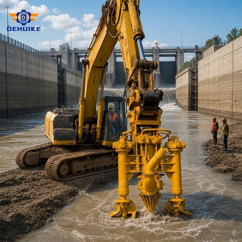
|
Model |
Discharge (DN) |
Flow (m³/h) |
Head (m) |
Typical work |
|
WJY50-20 |
80 |
50 |
20 |
Sump and trench cleanup |
|
WJY150-25 |
100 |
150 |
25 |
Wash-plant recovery, small pond |
|
WJY300-25 |
150 |
300 |
25 |
Canal dredging, lagoon maintenance |
|
WJY450-30 |
200 |
450 |
30 |
Aggregate transfer with lift |
|
WJY700-25 |
250 |
700 |
25 |
Long discharge runs |
|
WJY1000-20 |
300 |
1,000 |
20 |
Bulk reclamation, large circuits |
Two readings of that table matter. First, discharge size grows with flow, so the model choice is also a hose and pipeline decision. Second, the head figures cluster between 18 and 40 m across the whole range, which tells you the family is built for moving volume over moderate distance rather than for pressure. If your site needs 90 m of head, this is not the tool; you need a different pump and probably a booster.
What hydraulic drive buys you
The reason crews choose hydraulic over electric is rarely efficiency. It is usually one of three things.
No cable in the water. An electric submersible in a gravel pit is exposed to the most hostile cable environment there is: excavator tracks, jagged rock, drifting debris, and a rising and falling water line. Cable damage and moisture in the winding are the two failures that end electric pumps in this service. A hydraulic unit carries oil through a hose instead, and the hose can be routed where nothing runs over it.
Torque you can modulate. When a sand bar slumps into the intake, an electric motor keeps its speed and current climbs until the breaker or the overload trips. A hydraulic motor can be slowed or stalled briefly by the operator without electrical damage, then brought back up. On a dredge where the face collapses every few minutes, that difference is the whole shift.
Stepless speed without a drive. Throttling the oil flow gives roughly 800 to 1,600 rpm on most of these units, which lets the operator hold line velocity at the right value as the material changes. No VFD, no separate cooling for electronics, no parameter set to lose.
What it charges you is equally real, and it shows up on the hydraulic side:
You need a power pack or a carrier circuit with enough flow and pressure. An excavator's auxiliary circuit is often smaller than buyers assume.
The oil has to be cooled. A 300 kW hydraulic circuit rejects a lot of heat into a reservoir that is usually too small on a borrowed machine.
Return-line backpressure at the case drain can blow the motor shaft seal. This is the single most common hydraulic failure we hear about, and it is a plumbing mistake, not a pump fault.
Quick couplers are a contamination path. Every connect and disconnect brings a little grit into a circuit that needs clean oil.
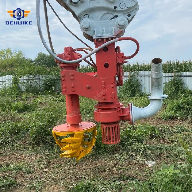
|
Question |
Hydraulic drive |
Electric submersible |
|
Power source on site |
Carrier circuit or diesel power pack |
Mains or generator, cable run |
|
Cable exposure |
None in the water |
High in pits and dredge cuts |
|
Speed control |
Stepless by oil flow, no VFD |
Fixed, or VFD with its own enclosure |
|
Behaviour on a slump |
Can be slowed or stalled briefly |
Current climbs until protection trips |
|
Extra infrastructure |
Oil cooling, reservoir, filtration |
Starter, protection, cable management |
|
Maintenance skills |
Hydraulic technician |
Electrician and mechanical fitter |
Water numbers are not slurry numbers
The published table is a water calibration: clean water, 1,450 rpm, standard intake. Put sand into the same pump and three things move at once.
The mixture gets heavier. At 1.25 specific gravity the column in the discharge line weighs a quarter more than water, and every metre of static lift costs proportionally more pressure. Head falls.
Friction rises. Solids increase the resistance in the line, and coarse particles add a component that clean-water tables do not describe. Long runs with bends suffer most.
The hydraulic motor works harder. More pressure for the same flow means more oil pressure and more heat, which loops back to the cooling question above.
The practical consequence is that you should not buy the model whose flow matches your target and then hope. Take the duty to the supplier with the actual material: grading, specific gravity, solids by volume, and the route. Ask for the expected flow and head at that condition, and accept that the honest answer is a range. Where the answer cannot be given with confidence, the safer move is a larger discharge line, not a bigger motor.
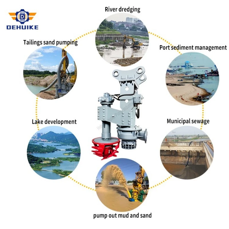
Keep the line above the settling point
Coarse material needs velocity to stay in suspension. Around 2.5 to 3.2 m/s is the working band for sand and gravel in a rubber or steel line; below roughly 2.5 m/s the heavier fraction starts to drop out, and once a dune forms it grows fast.
Three causes account for most blockages we see:
Velocity loss from route changes. Extra bends, a longer run, a raised discharge point, or a switch from steel pipe to a larger hose all reduce velocity. The pump did not change; the line did.
Air entering at the intake. A suction that draws near the surface pulls a vortex and the pump loses prime intermittently. Flow drops, velocity drops, and the dune forms downstream of the pump rather than at the intake.
Oversized solids. A pump built for sand is not a pump built for cobbles. If the intake keeps taking material above the passage size, the blockage is in the wrong place to fix by throttling.
The counterintuitive rule: to keep a slurry line moving, choose the pipe diameter from the velocity you need, then choose the pump that delivers the flow through that diameter. Buyers usually do it the other way around, and then discover that a 300 mm hose on a 200 m³/h duty runs at about 0.8 m/s, which is a settling chamber with a pump attached.
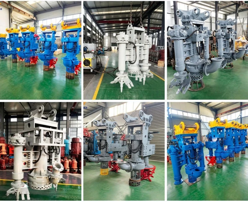
Experience and Markets | Documentation that Supports Better Project Decisions
For project review, request documentation that matches the intended transfer method. Useful information includes technical drawings, operating instructions, spare-parts identification, inspection records, packing details, warranty conditions, and technical support contacts.
A transfer system should be assessed according to its real source material, route layout, and receiving condition. This approach helps distributors, contractors, and engineering buyers compare proposals on a consistent technical basis.
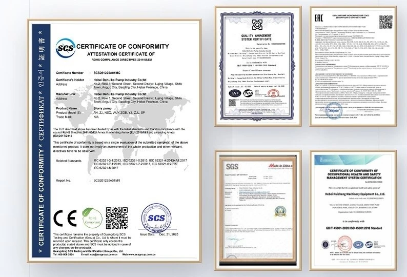
Our Service | Provide the Transfer Details We Need
Send the following information for a hydraulic sludge transfer pump proposal:
Source location and sludge condition
Estimated solids level, water content, and material characteristics
Required flow and total head
Route drawing with line length, elevation, bends, and discharge destination
Operating hours, stop-start pattern, and line-cleaning method
Available hydraulic power or carrier information
Requested supply scope for pump, drive, inlet equipment, hoses or pipes, support, spares, and documents
With this information, the supplier can recommend a model reference and define the required transfer package more accurately.
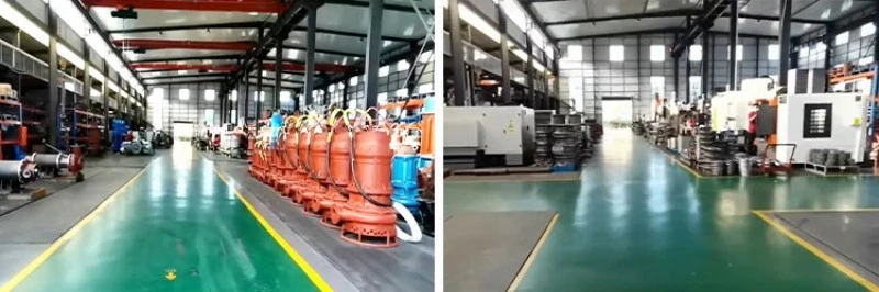
Installation, Maintenance and Precautions | Keep the Route Ready for Transfer
During operation, monitor delivery stability, vibration, leakage, hydraulic temperature, hose condition, unusual sound, and sludge accumulation in the line. A change in water content or solids concentration can change the transfer condition and should be reviewed promptly.
For maintenance, establish clear inspection points, spare-parts identification, line-cleaning responsibilities, and energy-isolation procedures. Do not operate against a blocked line, reverse flow, unknown debris, incompatible chemical condition, or unapproved temperature condition.
FAQ
Q1. Which models are included in this page?
This page includes WJY120-18, WJY350-25, WJY450-25, WJY600-30, and WJY1000-18 as selected transfer references.
Q2. What is the flow range of the selected models?
The selected range starts at 120 m3/h for WJY120-18 and reaches 1000 m3/h for WJY1000-18.
Q3. Which selected model has the highest total head?
WJY600-30 has the highest listed total head in this selected group at 30 m.
Q4. Can flow rate be used as dry sludge output?
No. Flow rate describes pumped mixture volume. Dry sludge output depends on actual solids concentration and density.
Q5. Can the outlet caliber be used as the final pipe or hose size?
Confirm the connection drawing before selecting pipe, hose, flange, or adaptor components.
Q6. Can the pump handle every type of sludge?
Final suitability depends on sludge consistency, solids content, fibre content, temperature, chemical condition, and the selected construction.
Q7. What information is needed for a quotation?
Provide the sludge description, source-to-destination route, required duty, hydraulic information, operating schedule, and supply scope.
Q8. Can the system be used for stop-start transfer work?
The stop-start plan, line-clearing method, and restart procedure should be defined for the actual route and sludge condition before operation.

Request a Sludge Transfer Duty Review
Send your transfer route, sludge condition, and required duty point for a Hydraulic Sludge Transfer Pump proposal. Our team can help you define the suitable model reference and the required project configuration.
Hot Tags: hydraulic sludge transfer pump, China hydraulic sludge transfer pump manufacturers, suppliers, factory