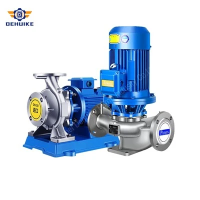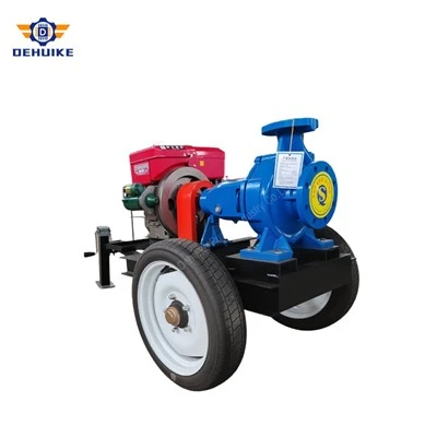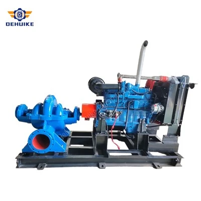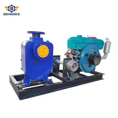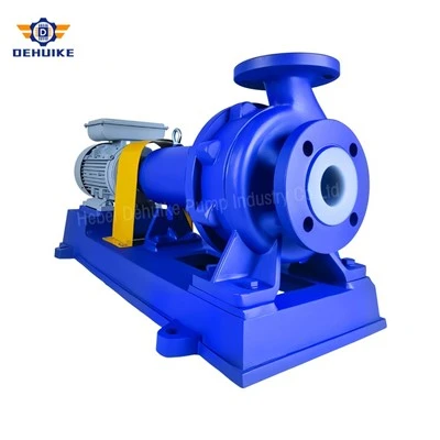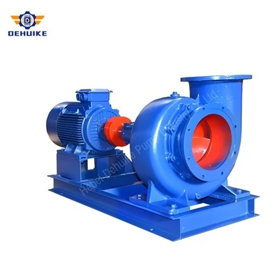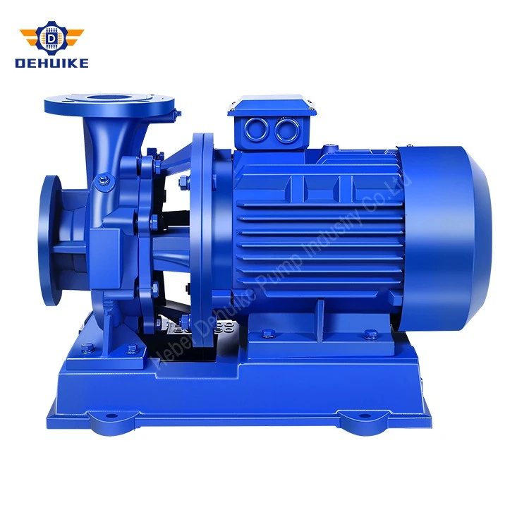
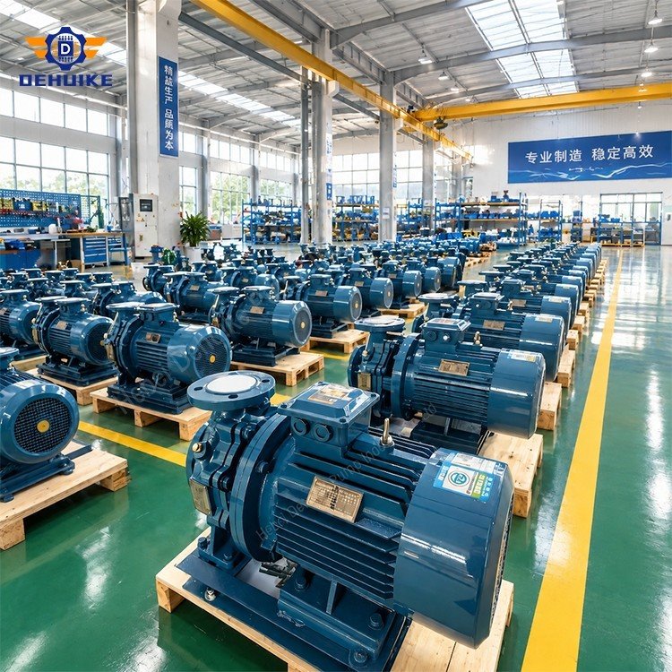
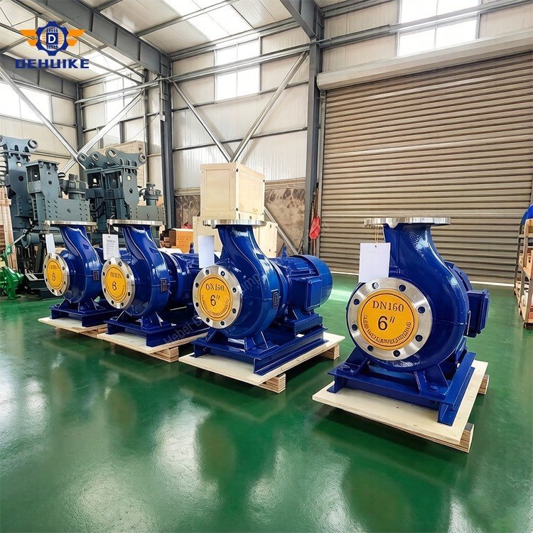
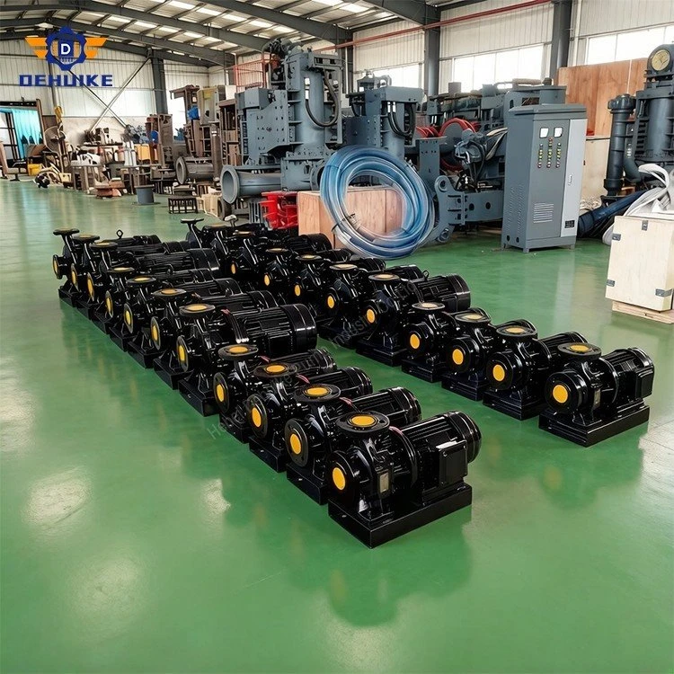
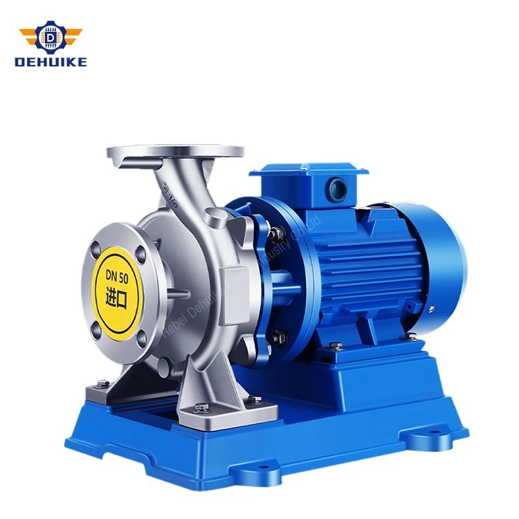
Hebei Dehuike Pump Industry Co., Ltd. is one of the most reliable manufacturers and suppliers of high pressure inline pump in China. With abundant experience, we are committed to providing high quality customized pumps with competitive price. Welcome to wholesale bulk high pressure inline pump for sale here from our factory. Also, pricelist is available.
Introduction & High-Pressure Pumping Mission
Engineering Definition: A high pressure inline pump is a pipeline-integrated centrifugal machine engineered to generate and sustain discharge heads exceeding 80 meters - equivalent to working pressures above 8 bar - within a single impeller stage, while maintaining the coaxial in-line flange geometry that allows direct insertion into straight piping runs. Unlike standard-duty inline pumps designed for moderate building circulation at 12 to 50 meters, a high pressure inline pump is purpose-built for applications where the fluid must be pushed to great heights, across vast horizontal distances, or against significant terminal equipment backpressure - all without the mechanical complexity of multi-stage impeller stacking.
The defining challenge of high-pressure inline pump engineering is not flow generation but pressure containment. At 150 meters of differential head - the upper boundary of the DHK Pump single-stage high-pressure program - the volute casing walls, flange joints, and mechanical seal chamber must continuously contain internal hydrostatic pressures exceeding 15 bar (1.5 MPa) while the impeller rotates at 2900 r/min. This demands a fundamentally different engineering approach from standard-duty pumps: thicker-section ductile iron castings, reinforced flange geometries, pressure-balanced mechanical seal designs, and dynamically balanced high-speed rotating assemblies that resist both hydraulic thrust and pressure-induced casing deformation.
The DHK Pump high pressure inline pump program covers differential heads from 80 meters up to 153.6 meters within a single stage, with rated flows spanning 4.4 m³/h for compact high-rise zone loops up to 260 m³/h for heavy industrial distribution. Motor ratings range from 4.0 kW on the smallest high-head frames to 90 kW on the largest capacity units, all operating at 2900 r/min (two-pole) for maximum head-per-stage density. Standard cast iron casings contain working pressures to 1.6 MPa, while the high-pressure program utilizes QT450-10 ductile iron volutes certified to 2.5 MPa containment. Fluid temperature windows run from -10°C to +80°C in standard water service, with specialized seal and elastomer packages extending service to +120°C for boiler feed applications.
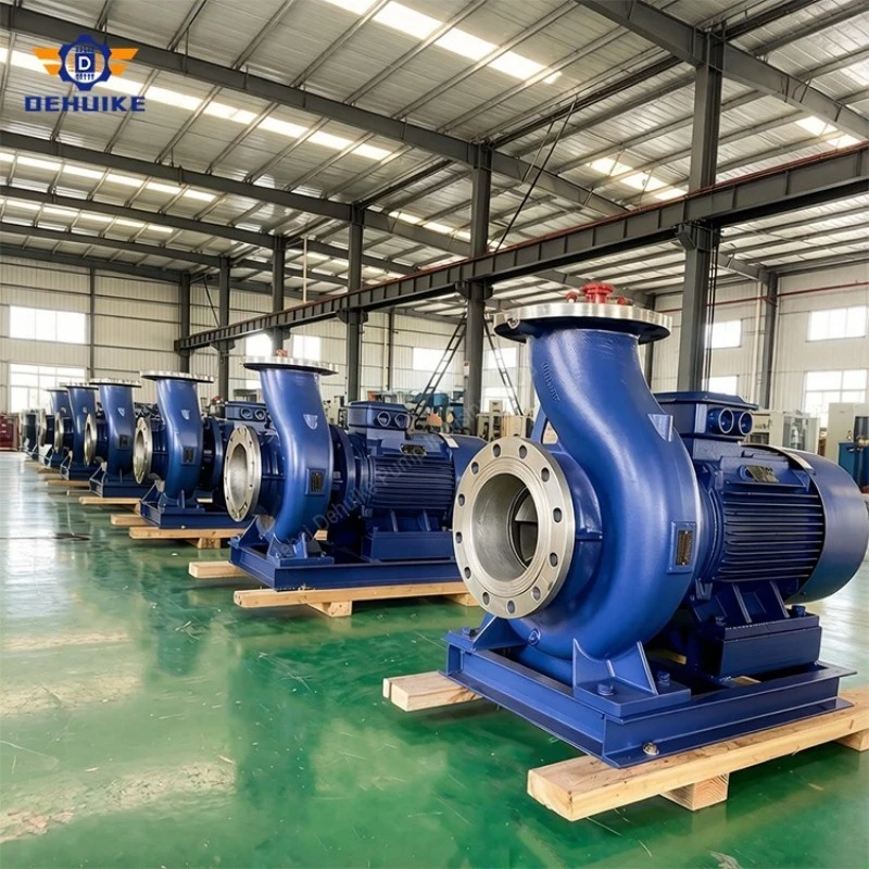
Pressure Containment Engineering & Casing Integrity
Pressure Vessel Philosophy: At discharge heads above 80 meters, the pump casing transitions from a simple fluid conduit into a pressure vessel. Every design decision governing the volute, flange, and seal chamber must be re-evaluated against the principles of sustained-pressure containment engineering, cyclic fatigue resistance, and elastic deformation control.
Ductile Iron Volute Architecture
Standard ISG/ISW inline pumps utilize HT250 pearlitic grey cast iron for volute construction - an excellent material for moderate-duty water service up to 1.6 MPa. However, the high pressure inline pump program mandates QT450-10 nodular ductile iron as the baseline casing material. Ductile iron's microstructure - spherical graphite nodules dispersed in a ferritic-pearlitic matrix - delivers a minimum tensile strength of 450 MPa with elongation exceeding 10 percent, providing both the strength to contain high internal pressures and the ductility to absorb hydraulic shock without brittle fracture. Volute wall sections are computationally verified using finite element analysis (FEA), with minimum wall thicknesses maintained at 1.5 times the value calculated by thin-cylinder stress equations, providing a built-in corrosion and erosion allowance that preserves containment integrity across decades of service.
Reinforced Flange Geometry & Gasket Sealing
High-pressure service demands flange geometry engineered beyond standard DIN PN16 drilling. The high pressure inline pump series integrates full-face raised-face flange profiles machined to DIN EN 1092-2 PN25 or ANSI B16.5 Class 300 specifications, with bolt circle diameters and stud counts sized to resist flange rotation under maximum internal pressure. Spiral-wound stainless steel gaskets with graphite filler - rated for continuous service at 250°C and 25 bar - are specified for all high-pressure models. Flange-to-volute transitions are radiused and thickened to eliminate stress concentration at geometric discontinuities, the most common origin site for pressure-fatigue cracking in lesser-engineered pump casings.
Hydrostatic Proof Testing Protocol
Every high pressure inline pump volute undergoes 100% hydrostatic proof testing at 1.5 times the maximum allowable working pressure (MAWP) before assembly. For standard high-pressure models rated at 1.6 MPa working pressure, the test pressure reaches 2.4 MPa (24 bar); for ductile iron high-pressure executions rated at 2.5 MPa, the proof test pressure reaches 3.75 MPa (37.5 bar). The casing is pressurized with filtered water for a minimum hold period of 30 minutes, with visual inspection of all external surfaces, flange joints, and threaded ports for weeping, sweating, or visible deformation. Only casings passing this witnessed test proceed to rotating-assembly installation.
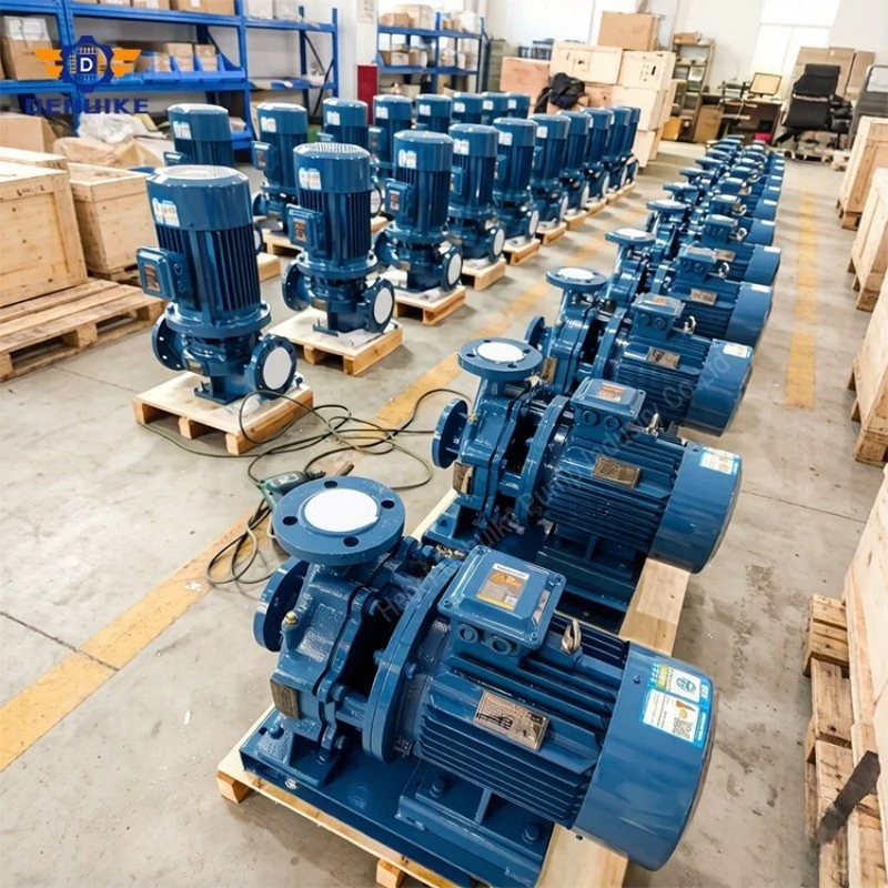
High-Pressure Specifications & Performance Data
The performance data below is extracted from factory dynamometer test records for the high pressure inline pump program, focusing specifically on models delivering heads at or above 80 meters. All ratings are verified on automated closed-loop test beds to ISO 9906:2012 Grade 2B acceptance criteria, with certified performance curves issued for each unit. The 'Boost Head (bar)' column provides a direct engineering conversion - divide the meter head by 10.2 to obtain the pressure differential in bar that the pump adds to the incoming supply.
Engineering envelope summary: the high pressure inline pump program spans discharge heads from 80 m to 153.6 m (approximately 7.8 to 15.1 bar of added pressure), with flows from 4.4 m³/h to 200 m³/h per unit. Maximum casing working pressures reach 1.6 MPa in standard cast iron and 2.5 MPa in ductile iron executions. Motor power ranges from 4.0 kW to 90 kW at 2900 r/min. All models are available with A, B, and (on selected frames) C impeller trim variants for precise duty-point matching without throttling-valve energy waste.
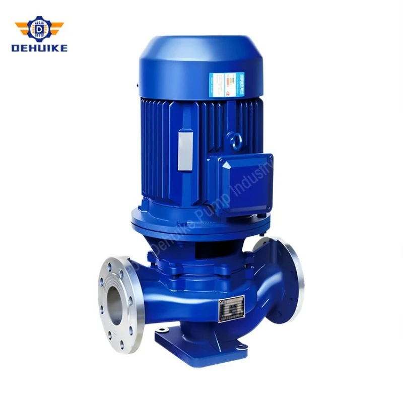
Table 1: Compact High-Pressure Models (DN40 to DN65, 80 m to 128 m Head)
|
Model |
Rated Flow (m³/h) |
Flow (L/s) |
Head (m) |
Boost Head (bar) |
Motor (kW) |
Speed (r/min) |
NPSHr (m) |
|
40-250 |
6.3 |
1.75 |
80.0 |
~7.8 |
7.5 |
2900 |
2.3 |
|
40-250A |
5.9 |
1.64 |
70.0 |
~6.9 |
5.5 |
2900 |
2.3 |
|
40-250B |
5.5 |
1.53 |
60.0 |
~5.9 |
4.0 |
2900 |
2.3 |
|
50-315(I) |
25.0 |
6.94 |
125.0 |
~12.3 |
30.0 |
2900 |
2.5 |
|
50-315(I)A |
23.7 |
6.58 |
113.0 |
~11.1 |
22.0 |
2900 |
2.5 |
|
50-315(I)B |
22.5 |
6.25 |
101.0 |
~9.9 |
18.5 |
2900 |
2.5 |
|
50-315(I)C |
20.6 |
5.72 |
85.0 |
~8.3 |
15.0 |
2900 |
2.5 |
|
65-315 |
25.0 |
6.94 |
125.0 |
~12.3 |
30.0 |
2900 |
2.5 |
|
65-315A |
23.7 |
6.58 |
113.0 |
~11.1 |
22.0 |
2900 |
2.5 |
|
65-315B |
22.5 |
6.25 |
101.0 |
~9.9 |
18.5 |
2900 |
2.5 |
|
65-315C |
20.6 |
5.72 |
85.0 |
~8.3 |
15.0 |
2900 |
2.5 |
|
80-315 |
35.0 |
9.72 |
128.0 |
~12.5 |
37.0 |
2900 |
3.0 |
|
80-315A |
32.5 |
9.0 |
112.6 |
~11.0 |
30.0 |
2900 |
3.0 |
Table 2: Heavy Industrial High-Pressure Models (DN80 to DN150, 125 m to 153.6 m Head)
|
Model |
Rated Flow (m³/h) |
Flow (L/s) |
Head (m) |
Boost Head (bar) |
Motor (kW) |
Speed (r/min) |
Weight (kg) |
|
80-315(I) |
100.0 |
27.8 |
125.0 |
~12.3 |
75.0 |
2900 |
675 |
|
80-315(I)A |
95.0 |
26.4 |
113.0 |
~11.1 |
55.0 |
2900 |
535 |
|
80-315(I)B |
90.0 |
25.0 |
101.0 |
~9.9 |
45.0 |
2900 |
420 |
|
80-350 |
50.0 |
13.9 |
150.0 |
~14.7 |
55.0 |
2900 |
570 |
|
80-350A |
44.5 |
12.4 |
138.4 |
~13.6 |
45.0 |
2900 |
470 |
|
80-350B |
41.0 |
11.4 |
131.4 |
~12.9 |
37.0 |
2900 |
440 |
|
100-315 |
100.0 |
27.8 |
132.0 |
~12.9 |
75.0 |
2900 |
689 |
|
100-315A |
95.0 |
26.4 |
119.0 |
~11.7 |
55.0 |
2900 |
549 |
|
100-315B |
90.0 |
25.0 |
106.6 |
~10.5 |
45.0 |
2900 |
439 |
|
100-350 |
100.0 |
27.8 |
153.6 |
~15.1 |
90.0 |
2900 |
950 |
|
100-350A |
87.0 |
24.2 |
145.6 |
~14.3 |
75.0 |
2900 |
830 |
|
100-350B |
82.0 |
22.8 |
138.6 |
~13.6 |
55.0 |
2900 |
600 |
|
125-315 |
160.0 |
44.4 |
133.0 |
~13.0 |
90.0 |
2900 |
790 |
Balanced Mechanical Seal Engineering for High Pressure
The Seal Challenge: The mechanical shaft seal is the single most pressure-sensitive component in any high pressure inline pump. At heads above 80 meters, the seal chamber sees internal pressures that would destroy a standard unbalanced seal within hours. High-pressure seal engineering is therefore a specialized discipline within pump design - one that separates reliable high-pressure service from chronic failure.
Pressure-Balanced Seal Face Geometry
Standard mechanical seals operate with full chamber pressure acting across the entire face area, producing high closing forces that crush the lubricating fluid film between the faces and cause dry-contact thermal cracking. The high pressure inline pump employs balanced (step-shaft) mechanical seals, where a precision-machined shoulder on the shaft sleeve reduces the effective hydraulic face area by a calculated balance ratio (typically 0.70 to 0.75). This means only 70 to 75 percent of chamber pressure translates into closing force on the seal faces - enough to maintain positive contact and prevent leakage, but not so much that the inter-face fluid film is squeezed dry. The result: face pressure stays below the PV (pressure-velocity) limit of the selected face material, and the seal achieves its design service life of 15,000+ operating hours even at maximum rated discharge pressures.
Face Material Selection for High-Pressure Service
High-pressure service demands face materials capable of withstanding elevated PV loading without thermal distress. The standard high-pressure seal face combination features reaction-bonded silicon carbide (SiC) against silicon carbide (SiC/SiC) - a material pairing with exceptional thermal conductivity (130 W/m·K), hardness (2500 HV), and chemical inertness. For applications where the pumped medium may carry trace abrasive particulates, tungsten carbide against carbon-graphite (TC/C) is specified, offering superior embedding tolerance. Secondary elastomeric components - O-rings and wedges - are molded from high-grade fluorocarbon (FKM / Viton) rated for continuous service at +200°C, ensuring sustained elastic sealing force under cyclic pressure and temperature fluctuation.
Seal Chamber Pressure Management
In ultra-high-pressure models exceeding 120 meters of head, the seal chamber is actively pressure-managed through an internal recirculation line that bleeds high-pressure seal chamber fluid back to the pump suction. This controlled depressurization reduces the absolute pressure that the seal faces must contain, extending both face life and elastomer service interval. The recirculation flow path is integrated within the pump casing - no external piping is required - and the bleed rate is engineered to maintain seal chamber pressure within the balanced seal's optimal operating envelope under all duty conditions.
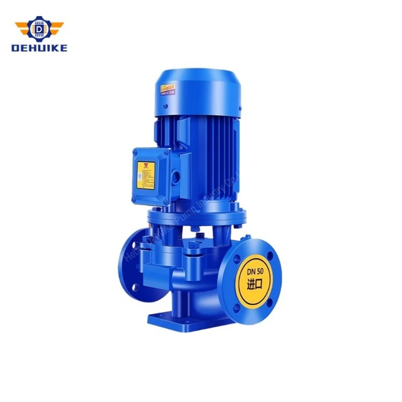
Our Advantages - Manufacturing Heritage & Factory Capabilities
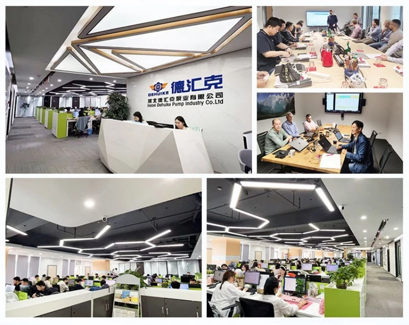
Vertically Integrated Manufacturing Complex
- Foundry Control: In-house furan resin-bonded sand casting with medium-frequency induction melting furnaces, real-time optical emission spectrometry (OES) chemistry verification on every melt, and microscopic metallurgical examination of pearlitic matrix density. Ductile iron production includes magnesium treatment stations and inoculation control for consistent nodularity above 85 percent.
- Precision Machining: Multi-axis CNC horizontal machining centers for volute, motor stool, and seal chamber finishing, with single-setup machining maintaining concentricity and perpendicularity within 0.012 mm tolerance. CMM (coordinate measuring machine) verification on all critical dimensional interfaces.
- Hydraulic Testing: Computerized closed-loop dynamometer test facility with electromagnetic flowmeters (Class 0.2 accuracy), digital pressure transmitters, and power analyzers, producing certified 5-point performance curves (Q, H, efficiency, power, NPSH) to ISO 9906 Grade 2B for every unit. Multi-channel vibration and acoustic emission screening ensures mechanical integrity before dispatch.
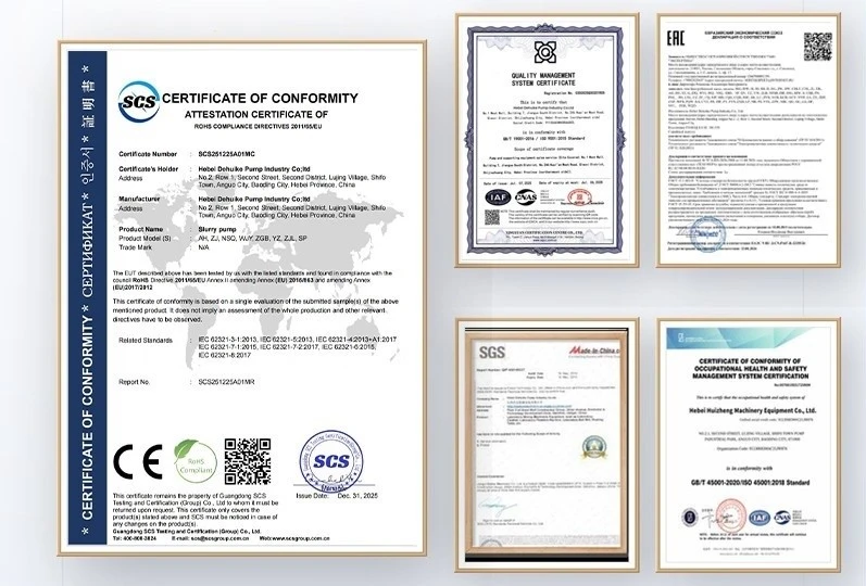
- Quality System: ISO 9001:2015 quality management system governing every production stage from raw material procurement through final paint and crating, with documented nonconformance tracking and corrective-action closure protocols.
Export Track Record & Regional Engineering References
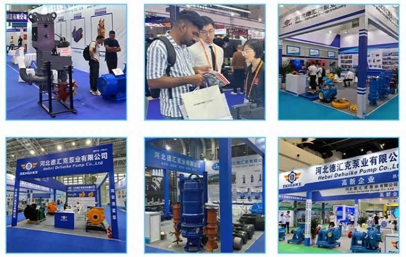
DHK Pump equipment has been deployed across more than 50 countries, with high-pressure inline pump installations including: high-rise residential boosting systems in Southeast Asia (Philippines, Vietnam, Indonesia); industrial process cooling circuits in North American manufacturing plants; boiler feed pressurization skids in Middle Eastern district heating networks; and long-distance irrigation pipeline transmission systems across African agricultural projects. Each export project is documented with EN 10204 3.1 material certificates, witnessed hydrostatic test records, and certified factory performance curves.
Application Scenarios for High-Pressure Inline Service
1. Ultra-High-Rise Residential & Commercial Water Supply
Buildings exceeding 25 to 30 stories require zone pressures that push single-stage pumps into their high-head envelope. A 100-meter tower with 2.0 bar minimum terminal pressure at the penthouse demands a booster generating at least 12 bar of differential - directly within the 125 m (12.3 bar) operating range of the 50-315(I) and 65-315 high-pressure models. The single-stage architecture provides this pressure with one impeller, one seal, and one bearing set - dramatically simpler to maintain than a multi-stage unit delivering equivalent head, and with shorter shaft geometry that resists whirling at high rotational speeds.
2. Industrial Boiler Feed & Hot Water Circulation
Steam boiler plants operating at pressures up to 1.0 MPa (10 bar) require feedwater pumps capable of overcoming the boiler's internal steam pressure plus piping friction and static lift - typically demanding 12 to 15 bar of feed pump differential. The 100-350 model, generating 153.6 meters (15.1 bar) at 100 m³/h with 90 kW motor, is purpose-engineered for this service. High-temperature executions utilize fluoroelastomer (FKM) seals, silicon carbide faces, and an extended cooling stool that protects motor bearings from thermal migration, handling feedwater temperatures up to +120°C reliably.
3. Long-Distance Pipeline Transmission & Remote Water Delivery
Rural water supply networks, mining camp distribution systems, and agricultural irrigation projects frequently pump water across distances of several kilometers through buried pipelines. Long-distance pipeline friction accumulates substantial head loss - frequently requiring 10 to 15 bar of continuous pumping pressure at the source station. High pressure inline pumps installed at pipeline origin points or intermediate boost stations maintain transmission flow against cumulative line friction, with the single-stage architecture providing high flow capacity (up to 200 m³/h on DN150 frames) at the discharge pressures required to reach remote consumption nodes.
4. Reverse Osmosis Feed & High-Pressure Washdown Systems
Industrial reverse osmosis (RO) membrane systems require feed pressures of 8 to 15 bar depending on membrane array design and source water salinity. The high pressure inline pump provides this feed pressure in a compact pipeline-integrated format, with stainless steel (CF8 / CF8M) wetted components to prevent ferric ion contamination of the membrane feed stream. Similarly, industrial washdown and hydro-cleaning stations in food processing, mining, and marine facilities specify 8 to 12 bar nozzle feed pressures - the operating envelope of the 50-315, 65-315, and 80-350 model families.
Installation, Commissioning & Maintenance Protocol
High-Pressure Commissioning Discipline: High-pressure pump installations demand a more rigorous commissioning discipline than standard-duty service. Pressures above 10 bar amplify every installation imperfection - a misaligned flange that passes unnoticed at 4 bar becomes a serious leak at 15 bar; an unvented air pocket that causes minor cavitation at low pressure can shatter a mechanical seal face at high differential. The protocol below represents accumulated engineering best practice from three decades of field commissioning support.
Pre-Installation & Piping Preparation
- Piping Cleanliness: All upstream piping must be flushed, hydro-tested, and chemically cleaned before connecting to the pump. Pipe scale, weld slag, or construction debris trapped upstream will enter the high-pressure impeller at 2900 r/min and destroy the mechanical seal within minutes of first operation. Install a temporary 40-mesh Y-strainer on the suction line and monitor differential pressure across it during initial commissioning; remove the strainer only when verified clean.
- Flange Torque Protocol: High-pressure flanges require torqued bolt-up, not hand-tightening. Use calibrated torque wrenches following a star-pattern sequence (typically three passes at 30%, 60%, and 100% of specified torque). Spiral-wound gaskets must seat uniformly - inspect gasket extrusion visually after the first pressurization cycle. Never exceed rated bolt torque, as over-torquing causes flange rotation and gasket crushing that produces leaks worse than under-torquing.
- Pipe Support Independence: Independent pipe supports must carry the entire dead weight of the suction and discharge piping. The pump volute is not a pipe support - any static or dynamic pipe load transmitted to the casing distorts the seal chamber bore, producing angular seal face misalignment that no amount of field adjustment can correct.
Initial Startup & Pressure Verification
Before energizing the motor, fully vent the casing through the seal-chamber bleed valve until a continuous stream of bubble-free water flows. Verify rotation direction by briefly bumping the motor (1-second pulse) against a partially closed discharge valve. Start the pump with the discharge valve at 20 to 30 percent open to limit initial motor inrush and prevent sudden pressurization shock on cold piping. Slowly open the discharge valve over 30 to 60 seconds while monitoring motor amperage, discharge pressure, and casing vibration simultaneously. Record baseline operating parameters - pressure, flow, motor amps, vibration velocity, and seal-chamber temperature - on the commissioning data sheet for future comparison.
Scheduled Maintenance & Spares Strategy
Preventive maintenance for high-pressure inline service follows a risk-based schedule: monthly visual inspection of seal chamber weepage (zero droplets per minute is the standard), quarterly vibration trend analysis (baseline comparison trending rather than absolute thresholds), and annual motor winding insulation resistance testing with a 500V Megohmmeter (minimum 50 MOhms). DHK Pump supplies factory-assembled 'High-Pressure Spares Packs' containing balanced mechanical seal cartridges, spiral-wound gasket sets, casing O-rings, and matched SKF/NSK thrust bearing pairs - vacuum-sealed in VCI moisture-barrier packaging for 24-month shelf life guarantee. Every spares pack is lot-traced to the original pump serial number for material compatibility verification.
Commercial Procurement & Global Engineering Support
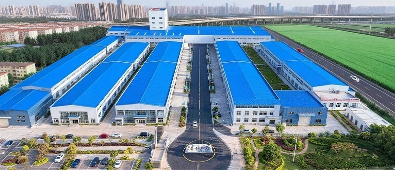
Manufacturer Profile: Hebei Dehuike Pump Industry Co., Ltd. (DHK Pump) is an established industrial fluid machinery manufacturer with over 30 years of continuous production heritage. Operating across 8,000+ square meters of advanced CNC workshops, computerized automated testing bays, and assembly lines supported by 900+ qualified supply chain partners, we serve mechanical contractors, consulting engineers, and plant operators in more than 50 countries worldwide.
Warranty & Certification: Every high pressure inline pump is backed by a comprehensive 24-month (two-year) mechanical warranty against defects in materials and factory workmanship (normal consumable wear parts excluded), plus factory performance certification to ISO 9906 Grade 2B.
Commercial Terms: Quotations are issued on Incoterms 2020 terms - FOB or CIF to the destination port - with mill certificates (EN 10204 3.1), witnessed hydrostatic test records, and certified performance curves in the document dossier.
Logistics: Shipments move by air freight for urgent project consignments of 50 to 500 kg, and by ocean freight for volume orders exceeding 500 kg, packed in certified ISPM 15 solid timber export crates with VCI moisture-barrier wrapping.
Engineering FAQ & High-Pressure Troubleshooting Guide
The technical questions below reflect the most frequent inquiries from consulting engineers, EPC contractors, and plant maintenance managers when specifying and operating high pressure inline pumps in demanding service environments.
Q1: When does single-stage high-pressure architecture outperform multi-stage stacking?
Single-stage high-pressure architecture is the superior choice when the required differential head falls within 150 to 153.6 meters (approximately 15 bar) and the application demands high flow at that head. Below this ceiling, the single-stage machine offers inherently stiffer shaft geometry (shorter L/D ratio resists dynamic deflection), dramatically simplified maintenance (one seal, one impeller, one bearing set to service), and eliminated inter-stage leakage losses that erode overall efficiency. Multi-stage stacking becomes necessary only when heads exceed approximately 150 to 200 meters, where a single impeller diameter would need to exceed practical structural limits to generate the required pressure.
Q2: Why is ductile iron mandatory instead of grey cast iron for high-pressure volutes?
Grey cast iron (HT250) is a brittle material with near-zero elongation - it contains internal graphite flakes that act as stress raisers and crack initiators. At pressures exceeding 1.0 MPa sustained, these micro-cracks propagate under cyclic pressure fatigue, eventually causing sudden, non-ductile casing fracture without warning. Ductile iron (QT450-10) contains spherical graphite nodules in a ferritic-pearlitic matrix that yields before fracture - the material deforms visibly under overload, providing operational warning and absorbing hydraulic shock without brittle failure. For any sustained pressure above 1.0 MPa, ductile iron is not an option; it is a structural safety requirement.
Q3: How is the mechanical seal's PV limit calculated and verified?
The pressure-velocity (PV) value is the product of seal face contact pressure (Pa) and mean rubbing velocity (m/s). For a balanced seal with balance ratio 0.75 operating at 15 bar chamber pressure on a 50 mm shaft at 2900 r/min: face pressure = 0.75 x 15 bar = 11.25 bar (1.125 MPa); mean velocity = pi x 0.05 m x 2900/60 = 7.59 m/s; PV = 1.125 x 7.59 = 8.5 MPa·m/s. This falls within the SiC/SiC limit of 15 MPa·m/s with a comfortable margin. The verification is performed for every model at maximum rated pressure to confirm face material and balance ratio suitability before production release.
Q4: What happens if the pump runs against a closed discharge valve?
Operation against a fully closed discharge valve is the most dangerous operating condition for a high pressure inline pump. With zero flow, all input energy converts to internal heat - fluid temperature rises rapidly (typically 1°C per minute per kW of motor power trapped in the volute). Within minutes, the mechanical seal faces lose their cooling fluid film, elastomers exceed their thermal limit, and vapor pressure rises until the seal cavitates and destructively vents. Discharge-side relief valves or minimum-flow bypass lines back to the suction source are mandatory safety provisions on all high-pressure installations to prevent deadhead operation.
Q5: Can a high pressure inline pump be used for hot water circulation?
Yes, with specified material upgrades. Standard high-pressure models handle water up to +80°C with standard EPDM elastomers and SiC/SiC seal faces. For boiler feed or heating circulation at +80°C to +120°C (or up to +150°C in specialized executions), the pump is configured with fluoroelastomer (FKM/Viton) secondary seals, an extended intermediate cooling stool that thermally isolates the motor from the casing, and a flush plan that routes cooler condensate or external cooling water through the seal chamber. These modifications are factory-specified and do not alter the pump's external dimensions or installation footprint.
Q6: What is the recommended spare parts inventory for a remote high-pressure installation?
For installations where factory lead time for replacement parts exceeds 30 days (remote mining camps, offshore platforms, rural district substations), maintain the following minimum spares inventory: one complete balanced mechanical seal cartridge (pre-set and ready to install - do not disassemble the cartridge before installation); one set of spiral-wound discharge and suction gaskets; one pair of front and rear casing wear rings (matched to the installed impeller trim); and one pair of motor drive-end and non-drive-end ball bearings. This inventory covers the most common field-replaceable failure modes and supports a 24-hour return-to-service target.

Hot Tags: high pressure inline pump, China high pressure inline pump manufacturers, suppliers, factory