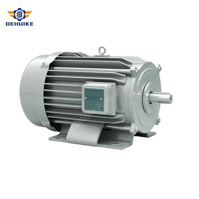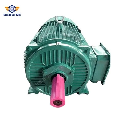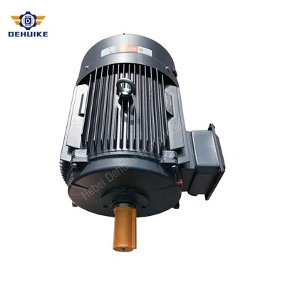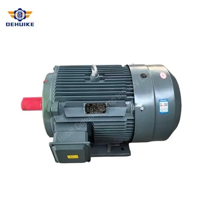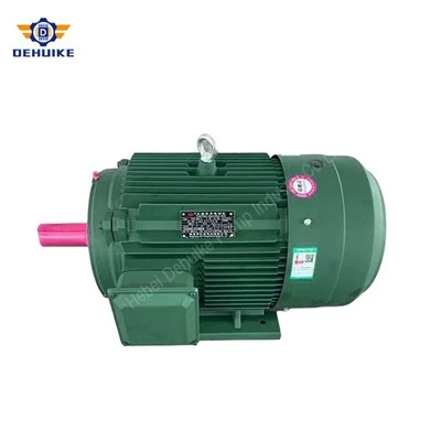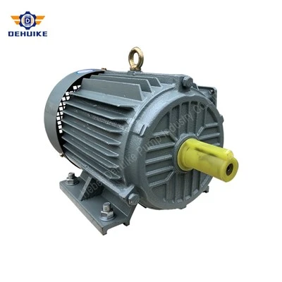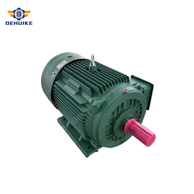
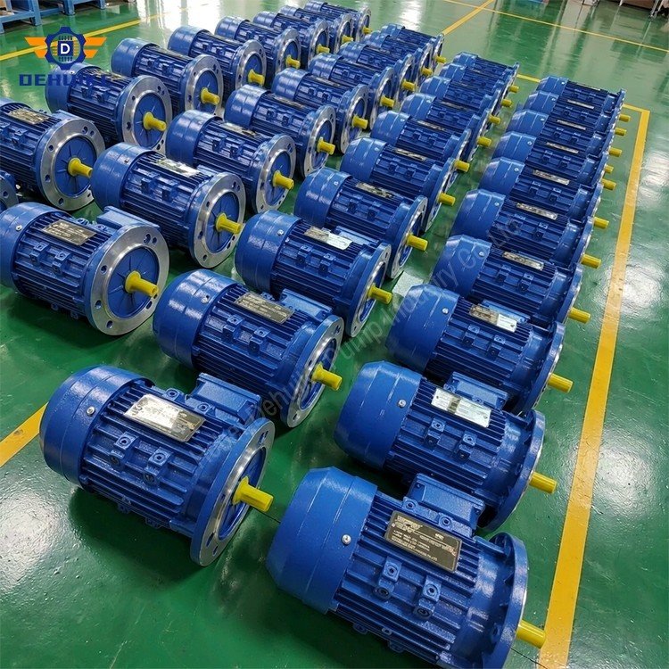
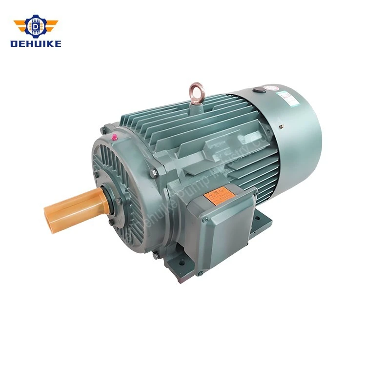
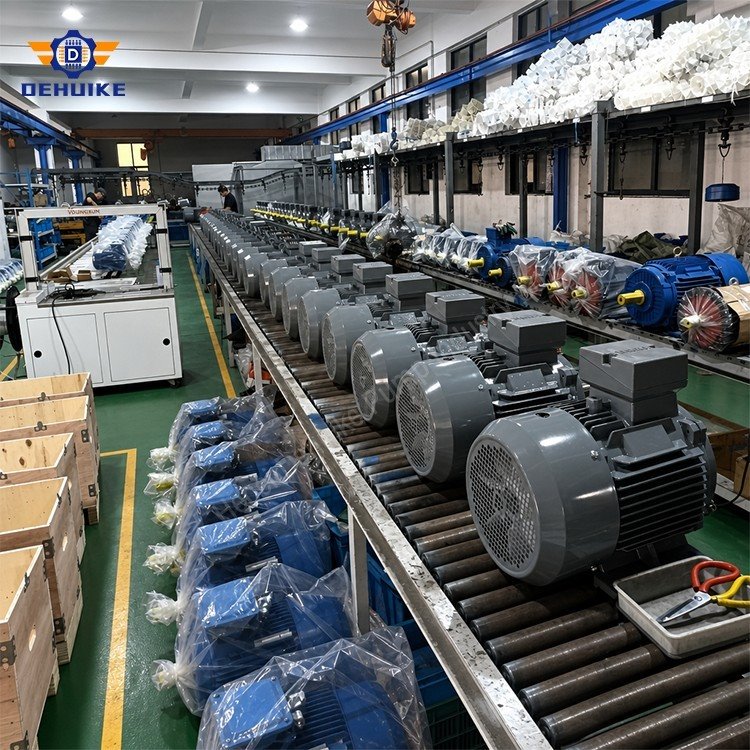
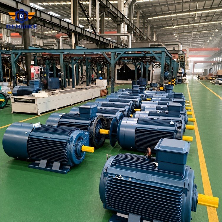
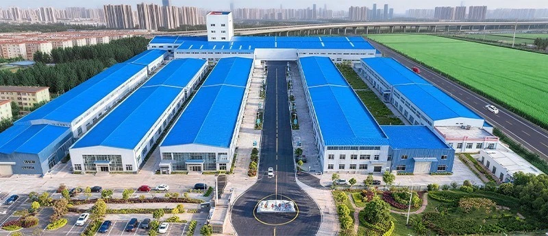
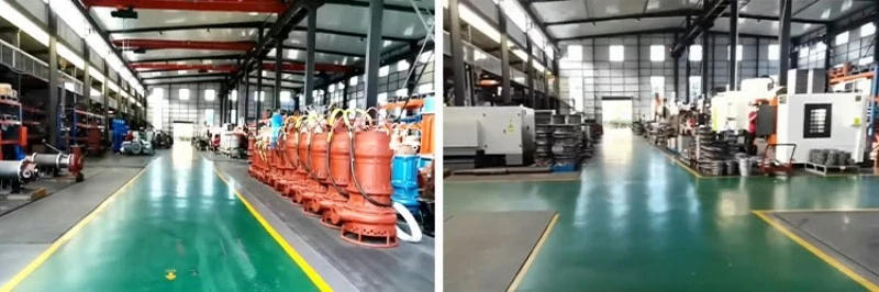
Hebei Dehuike Pump Industry Co., Ltd. is one of the most reliable manufacturers and suppliers of variable speed electric motor in China. With abundant experience, we are committed to providing high quality customized pumps with competitive price. Welcome to wholesale bulk variable speed electric motor for sale here from our factory. Also, pricelist is available.
Variable Speed Electric Motor for Demand-Matched Pumps, Fans, and Process Equipment
A Variable Speed Electric Motor is used when a machine must do more than run at one fixed operating point. It gives equipment designers and plant teams a way to align rotational speed with a changing process requirement, such as fluctuating flow demand, airflow demand, material feed rate, pressure condition, product viscosity, or production throughput. The useful result is not simply a motor that can run slower or faster. It is a drive system that can respond to the work the machine actually needs to perform.
In many installations, a fixed-speed motor is paired with mechanical or process restrictions to control output. A pump may be throttled to reduce flow, a fan may operate against a damper, or a conveyor may stop and start repeatedly to match downstream demand. A variable-speed approach can be considered where changing shaft speed is a more appropriate way to control the process. The final benefit depends on the driven machine, the load characteristic, the speed range, the control method, and the complete installation.
This article is written for configuration-based procurement. It does not state a fixed power range, voltage, frequency, speed range, torque value, enclosure, cooling arrangement, efficiency figure, drive rating, protection function, communications protocol, or certification. These details must be confirmed in the final technical schedule for the specified Variable Speed Electric Motor, compatible controller, and operating application.
Start With the Process Variable, Not the Motor Name
A variable-speed project begins with a process question: what must change, and why? The answer may be water flow, air volume, pressure, mixing intensity, belt speed, product dwell time, or machine cycle rate. When the process variable is clear, the engineering team can determine whether speed adjustment is the right control lever.
This sequence is important. A motor and drive combination should not be selected simply because a variable-frequency drive is available. The driven equipment must respond usefully to speed changes, and the process must be able to operate across the intended range. Some systems benefit directly from speed control; others require a more limited range, a different mechanical arrangement, or another method of regulation.
A complete project description should answer the following questions:
•Which process output must be controlled: flow, pressure, air volume, material movement, mixing, temperature response, or another variable?
•What is the normal operating point, and how often does demand depart from it?
•What is the useful minimum and maximum operating condition for the driven machine?
•Does the load behave as variable torque, constant torque, or another defined load type?
•Is the purpose energy management, process quality, soft acceleration, reduced mechanical stress, product handling, or coordinated line control?
•What sensors, feedback signals, or operator inputs will command the speed reference?
•What happens if the speed becomes too low, too high, or changes too quickly for the process?
By beginning with these answers, the buyer can move from a general request for speed control to a motor-drive package that has a defined function in the machine.
See the Motor and Drive as One Power-Drive System
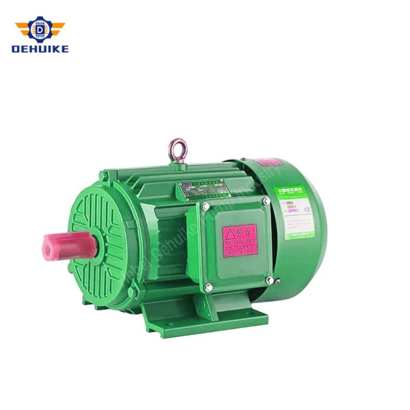
A variable-speed motor installation normally includes more than a motor. It may include a power converter, controller, speed-reference source, operator interface, protective devices, supply circuit, output cable, sensors, mechanical load, and software or parameter settings. These elements influence one another and should be reviewed as a complete power-drive system.
The U.S. Department of Energy describes an adjustable-speed drive as equipment that controls the rotational speed of motor-driven machinery. In practice, the controller changes the electrical supply presented to the motor so that shaft speed can be managed for the required application. A variable-frequency drive is one common form of adjustable-speed control used with AC motor systems.
The IEC 61800 series addresses adjustable-speed electrical power-drive systems. IEC 61800-5-1 applies to adjustable-speed electrical power-drive systems that include power conversion, control functions, and a motor or related elements. This framework is useful because it reinforces the correct engineering boundary: the drive is not only an electrical accessory, and the motor is not only a separate mechanical item. The selected components must work together.
|
Power-Drive Element |
Role in the Application Review |
|
Motor |
Converts controlled electrical energy into shaft motion for the driven machine. |
|
Drive or converter |
Manages the electrical output used to control motor speed and operating behavior. |
|
Process sensor |
Provides a signal such as pressure, flow, level, temperature, or position where feedback is required. |
|
Control logic |
Defines how the speed reference changes in response to process conditions or operator commands. |
|
Mechanical load |
Determines torque, inertia, operating range, and the consequences of speed change. |
|
Cable and installation |
Connects the components and must suit the approved electrical and environmental design. |
|
Protective functions |
Support safe and reliable operation according to the selected equipment and project requirements. |
A successful variable-speed project documents the interfaces between these elements. This makes commissioning more predictable and gives maintenance personnel a clearer reference when a setting or operating condition must be reviewed.
Match Speed Control to the Load Characteristic
The load characteristic is one of the most important pieces of information in a variable-speed selection. Different machines require different torque behavior as speed changes. A centrifugal pump or fan has a different operating relationship from a conveyor, extruder, positive-displacement pump, hoist, mixer, or crusher.
For centrifugal equipment, speed adjustment can be particularly relevant because the process output often changes with rotational speed. In such cases, pump and fan affinity relationships may be used by qualified engineers as part of system analysis. The actual result still depends on the hydraulic or airflow system, resistance curve, impeller condition, operating point, and controls. These relationships should guide engineering review, not be used to promise a universal reduction in energy use.
For constant-torque machinery, the drive must provide suitable torque across the defined operating range. Conveyors, mixers, material feeders, and certain processing machines may have load behavior that does not decrease in the same way as centrifugal equipment at lower speed. Low-speed operation may also change cooling conditions, mechanical lubrication behavior, product handling, and the required control response.
|
Load Category |
Typical Examples |
|
Variable torque |
Centrifugal pumps, fans, blowers |
|
Constant torque |
Conveyors, mixers, feeders, some positive-displacement machines |
|
Constant power |
Some machine-tool and winding applications |
|
High inertia |
Large fans, centrifuges, drums, rotating process equipment |
|
Sensitive process load |
Dosing, coating, batching, precision handling |
A variable-speed design should be based on the real load curve and process limits. Selecting only by nominal motor output can leave critical questions unresolved about low-speed torque, acceleration, overspeed protection, or the mechanical capability of the driven equipment.
Use Variable Speed to Improve Process Control
The practical value of speed control often appears in the way a machine responds to demand. Instead of operating at a fixed speed and using a restrictive element to reduce output, the system may adjust motor speed according to a measured process condition. This can support smoother control, reduced cycling, more stable product handling, or better alignment between production rate and machine output.
A variable-speed pump system, for example, may follow a pressure, flow, or level reference. A ventilation system may respond to temperature, airflow, or air-quality requirements. A conveyor may adjust material movement to coordinate with upstream and downstream equipment. A mixer may use different speeds at different stages of a recipe. A centrifugal process machine may require a managed acceleration and deceleration profile.
The speed-control objective needs to be stated in operational language. "Adjustable speed" is not enough. The project should define what the equipment is expected to maintain, the permitted operating band, the response time, the sensor used when applicable, and the action taken when a signal is missing or outside its expected range.
Define the Control Strategy
The selected strategy should account for the machine's physical behavior. A pressure system may not respond instantly to a speed change because of tank volume, pipework, and valve behavior. A conveyor may need acceleration limits to prevent product displacement. A mixer may require staged speed changes to avoid splashing or unstable material movement. A fan system may require minimum airflow for process safety or equipment cooling.
The control narrative should identify:
•The speed reference source and operating modes.
•The process value being monitored, if feedback control is used.
•Normal start, ramp, run, and stop behavior.
•Minimum and maximum permitted speed limits.
•Alarm, trip, and fallback actions for abnormal feedback or communication conditions.
•Operator authority and required access level for parameter changes.
This information turns a variable-speed drive into an understandable operating system instead of a panel component with unexplained settings.
Plan the Speed Range With Mechanical Reality
A motor may be capable of controlled operation over a defined range, but the connected machine also has a usable speed range. The pump, fan, gearbox, belt, coupling, bearing arrangement, seals, lubrication system, and process equipment must be reviewed for the intended conditions.
At low speeds, some machinery may experience reduced self-cooling, altered lubrication behavior, unstable process control, or insufficient flow for the equipment it supports. At high speeds, the load, noise, vibration, mechanical stress, hydraulic condition, or airflow system may become unsuitable. The approved operating window should therefore be selected around the full machine, not only the motor and drive.
This is especially important for pumps and fans. A reduced speed may be useful when demand falls, but the equipment must remain within a suitable hydraulic or aerodynamic operating range. A controlled drive does not make every low-flow or high-flow condition acceptable. The system curve, process requirement, and equipment manufacturer's guidance remain important.
For gear-driven machinery, a speed change at the motor affects every downstream rotating part. The gearbox ratio may remain fixed while the input speed changes, so output speed, torque demand, and equipment behavior must be reviewed together. For belt drives, pulley condition and belt speed may influence performance. For direct-coupled machines, the load must be assessed at the intended shaft speed.
Address Cooling and Thermal Conditions at Reduced Speed
Thermal behavior deserves special attention in variable-speed applications. Motor cooling can depend on the selected design and operating speed. When the motor operates at lower speed for extended periods, a shaft-mounted external fan may move less air than it does at nominal speed. The final cooling method and allowable operating conditions must be confirmed for the specific product configuration.
A variable-speed motor selection may therefore involve discussion of duty cycle, ambient temperature, speed range, enclosure, external airflow, load torque, and any auxiliary cooling option specified for the project. It is not appropriate to assume that every motor has the same capability at every reduced speed.
The installation layout matters as well. A motor placed in a hot enclosure or close to a heat source has less thermal margin than one installed in a clear, ventilated area. Dust, fibers, and contamination can also affect external cooling surfaces. The project should identify real ambient conditions and cleaning access before finalizing the motor package.
A practical thermal review asks:
•How long will the motor operate at reduced speed?
•What torque is required during that period?
•What cooling method is provided by the selected motor design?
•Is the surrounding air clean and available to the cooling path?
•Does the equipment enclosure retain heat?
•Will the process itself create high ambient temperature, moisture, or contamination?
These questions help prevent a variable-speed strategy from creating an unexamined thermal duty.
Coordinate Acceleration and Deceleration With the Process
For a pump, a rapid speed change can alter flow and pressure conditions. For a conveyor, it can shift material or create unwanted tension changes. For a fan, it can affect airflow and duct pressure. For a high-inertia machine, it can create an extended coast-down or require a defined braking strategy. The control parameters should be selected around what the process and mechanical train can accept.
The project team should specify whether the application needs gentle ramps, fast response, controlled stopping, free coast-down, emergency stopping, or coordination with another machine. These requirements should be represented in the control documentation and validated during commissioning according to site procedures.
Do not treat parameter changes as casual adjustments. A change in acceleration time, maximum speed, minimum speed, torque limit, or control mode can alter the behavior of the complete machine. Authorized changes should be documented and reviewed by personnel who understand both the drive and the process.
Integrate Sensors and Feedback With Clear Purpose
The sensor location, calibration, measurement range, signal handling, and failure response can affect the quality of speed control. A pressure sensor positioned in an unsuitable part of a pipe network may not represent the condition that matters to the user. A level sensor may require a deadband or delay to avoid repeated speed hunting. A conveyor sensor may need filtering to avoid reacting to transient product gaps.
The final control design should define what occurs if a sensor is disconnected, gives an invalid signal, or indicates a value outside the expected process range. The response may be a controlled stop, a fixed safe speed, an alarm, a manual mode, or another project-defined action. These decisions depend on risk assessment and process requirements.
Clear feedback design helps users trust the automatic system. Instead of seeing speed change without explanation, operators can understand which process condition is commanding the drive and what information must be checked if the machine behaves unexpectedly.
Apply Variable-Speed Drives Across Key Industries
A Variable Speed Electric Motor can be considered for many industrial and commercial systems where the driven load, controller, and operating range are suitable. The final configuration must reflect each application.
Pumping and Water Management
Water supply, circulation, irrigation, cooling, drainage, and process-transfer systems may experience changing demand. Speed control can be evaluated as a way to match pump output with a pressure, flow, or level requirement. The review should include pump curves, hydraulic system conditions, minimum-flow needs, suction conditions, valve arrangement, sensor location, and the consequences of a rapid speed change.
HVAC, Ventilation, and Air Treatment
Fans and air-handling equipment may follow building occupancy, process temperature, airflow demand, filter condition, or air-quality signals. A variable-speed arrangement should be evaluated with the fan curve, duct resistance, damper position, minimum ventilation requirement, motor cooling, and control sequence. The goal is to deliver the required air movement without treating every operating hour as a full-output condition.
Conveying and Packaging Lines
Material-handling systems often need to coordinate speed with filling, cutting, labeling, inspection, or downstream packaging. The drive review should address line synchronization, acceleration limits, belt or chain behavior, gearbox interface, product stability, sensor inputs, and emergency-stop logic. Variable speed can support smoother transitions when it is tied to the real operating sequence.
Mixing, Dosing, and Batch Processing
Mixing equipment may require different speeds during charging, blending, reaction, settling, or discharge. The selection should include the impeller, material properties, viscosity range, tank geometry, speed stages, torque demand, and required recipe control. The motor and controller should be assessed for the full batch cycle rather than only one mixing condition.
Compressors, Blowers, and Utility Skids
Industrial utility systems may need output to follow demand while maintaining process limits. The motor-drive package should be reviewed with compressor or blower behavior, surge or operating constraints where applicable, cooling conditions, load sequence, pressure control, and shutdown requirements. System engineering is essential because speed control can change the operating point of the complete utility network.
Machine Tools and Specialized Equipment
Tooling machines, test devices, winding equipment, surface-treatment systems, and special-purpose machinery may require selected speed profiles for product quality or operation. The project should define the speed reference, response requirement, mechanical transmission, guarding, and user-interface expectations before the motor configuration is confirmed.
Commission the System in Stages
Begin with document review. Confirm the motor data, controller data, wiring information, machine interface, control narrative, sensor details, and authorized parameter record. Qualified personnel should complete electrical checks and safety verification using applicable procedures.
Next, verify the mechanical arrangement. Inspect the motor mounting, coupling or belt system, gearbox interface, guards, cooling clearance, cable routing, and access for service. Confirm that the driven equipment can move safely through the planned speed range before entering automatic operation.
Then perform controlled functional checks. Verify local and remote commands where applicable, speed-reference response, sensor feedback, alarm handling, direction, acceleration, deceleration, and process interlocks. The exact test sequence must follow the machine and site procedure.
|
Commissioning Stage |
Purpose |
|
Configuration confirmation |
Checks that approved motor, drive, sensor, and control data correspond to the installed equipment. |
|
Mechanical readiness |
Reviews mounting, transmission, guards, cooling, lubrication provisions, and service clearance. |
|
Basic functional test |
Confirms direction, run command, stop command, and controlled speed response. |
|
Feedback validation |
Checks that the process signal is interpreted correctly by the control system. |
|
Operating-limit review |
Verifies the approved speed limits, ramp behavior, and interlock response. |
|
Process observation |
Confirms that the machine performs its required task across the intended operating conditions. |
|
Handover record |
Preserves authorized settings, documentation, and information needed for maintenance. |
A staged approach reduces the chance that a process problem will be incorrectly attributed to the motor or drive when the root cause is a sensor, mechanical restriction, control logic, or unsuitable operating point.
Maintain the Configuration, Not Just the Hardware
Variable-speed systems need maintenance attention at both the hardware and configuration levels. Motor condition, cable condition, cooling surfaces, mounting, and mechanical transmission remain important. In addition, the authorized control settings, feedback wiring, parameter records, and alarm history should be preserved and reviewed when changes occur.
A common service challenge occurs when a drive is replaced or parameters are changed without a current record of the original application settings. The system may still run, but it may no longer accelerate, limit speed, respond to feedback, or protect the process in the same way. Maintaining an approved parameter record helps prevent unintentional changes during repair work.
Routine observations can include operating sound, vibration, motor temperature trend, controller indications, fan or pump response, contamination at cooling areas, cable condition, and process stability. A meaningful change should lead to structured investigation by qualified personnel. Repeated resets or parameter changes without understanding the application can create a larger problem.
Keep these records with the equipment:
•Approved motor and drive identification.
•Current electrical and control drawings.
•Authorized parameter backup or setting list.
•Sensor and feedback description.
•Commissioning and handover notes.
•Maintenance history, alarms, and changes to the mechanical load or process.
This documentation supports efficient troubleshooting and makes future expansion or replacement work more reliable.
Build a Complete Variable-Speed Motor Inquiry
A complete inquiry gives the engineering team the information needed to review motor, drive, process, and installation compatibility together.
|
Inquiry Area |
Information to Provide |
|
Process objective |
The variable to be controlled and the reason speed adjustment is required. |
|
Driven equipment |
Pump, fan, conveyor, mixer, compressor, machine tool, or other load description. |
|
Load behavior |
Variable torque, constant torque, inertia, starting condition, and operating cycle. |
|
Speed requirement |
Normal operating point, intended range, minimum and maximum limits, and response needs. |
|
Supply and control |
Available electrical supply, proposed drive arrangement, control mode, and panel interface. |
|
Feedback |
Sensor type, measured process value, setpoint logic, and required behavior if feedback is unavailable. |
|
Mechanical interface |
Mounting, shaft connection, gearbox or belt arrangement, equipment layout, and service access. |
|
Environment |
Ambient conditions, cooling clearance, contamination, moisture, and maintenance constraints. |
|
Documentation |
Drawings, parameter records, inspection needs, marking, packaging, and destination requirements. |
For a replacement project, include photographs of the existing motor, drive panel, nameplate, cable route, connected machine, and sensor arrangement. Also explain why the present system is being replaced: process instability, expanded capacity, energy-management goal, damage, obsolete controls, or another confirmed reason. This evidence supports a more useful configuration review.
Frequently Asked Questions
Q: What is a Variable Speed Electric Motor used for?
A: It is used in systems where changing motor speed can help the equipment follow a changing process requirement. Common evaluations include pumps, fans, conveyors, mixers, compressors, packaging lines, and specialized machinery. The final motor-drive combination must be selected for the specific load and operating range.
Q: Is a variable-speed motor the same as a variable-frequency drive?
A: They are related but not identical. The motor provides shaft output, while a variable-frequency drive is one type of controller that manages the electrical supply used to adjust motor speed. The application should be reviewed as a complete motor-drive system.
Q: Can speed control reduce energy use?
A: It can be beneficial in applications where the machine can match output to demand, particularly for appropriate centrifugal pump and fan duties. The actual result depends on the system curve, operating schedule, control method, equipment condition, and installed operating range. No fixed saving should be assumed without project analysis.
Q: What is the most important information for a variable-speed pump application?
A: Provide the pump curve, required flow and pressure behavior, pipe-system condition, minimum-flow needs, suction conditions, control setpoint, sensor location, intended speed range, and operating schedule. The motor and drive should be selected with the complete hydraulic system.
Q: Can the motor operate continuously at low speed?
A: The answer depends on the selected motor design, cooling method, load torque, ambient conditions, operating time, and approved speed range. Low-speed thermal conditions must be confirmed for the exact application rather than assumed.
Q: Why are acceleration and deceleration settings important?
A: They influence mechanical stress, product handling, pressure changes, equipment inertia, and process response. The approved ramp settings should be selected around the machine and documented so later changes do not create unintended behavior.
Q: What happens if a feedback sensor fails?
A: The response should be defined by the project control design. It may involve an alarm, a controlled stop, a fixed fallback speed, manual operation, or another approved action. The correct approach depends on process requirements and risk assessment.
Q: Does this page list fixed motor or drive ratings?
A: No. Output, voltage, frequency, speed range, torque, controller rating, enclosure, communications, and compliance information must be confirmed for the final specified equipment. This article does not make unverified rating claims.

Hot Tags: variable speed electric motor, China variable speed electric motor manufacturers, suppliers, factory