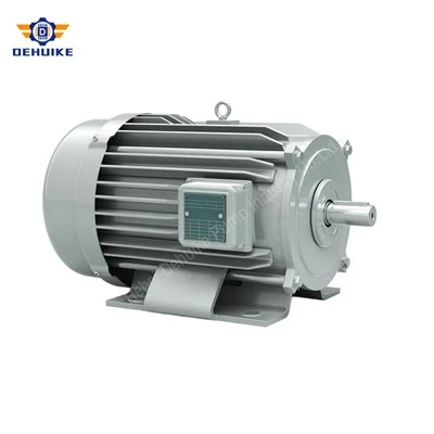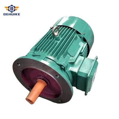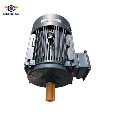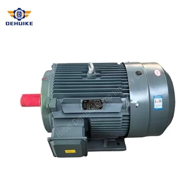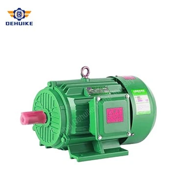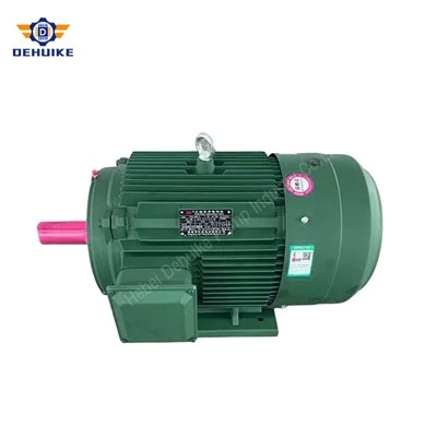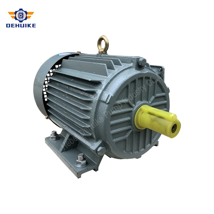
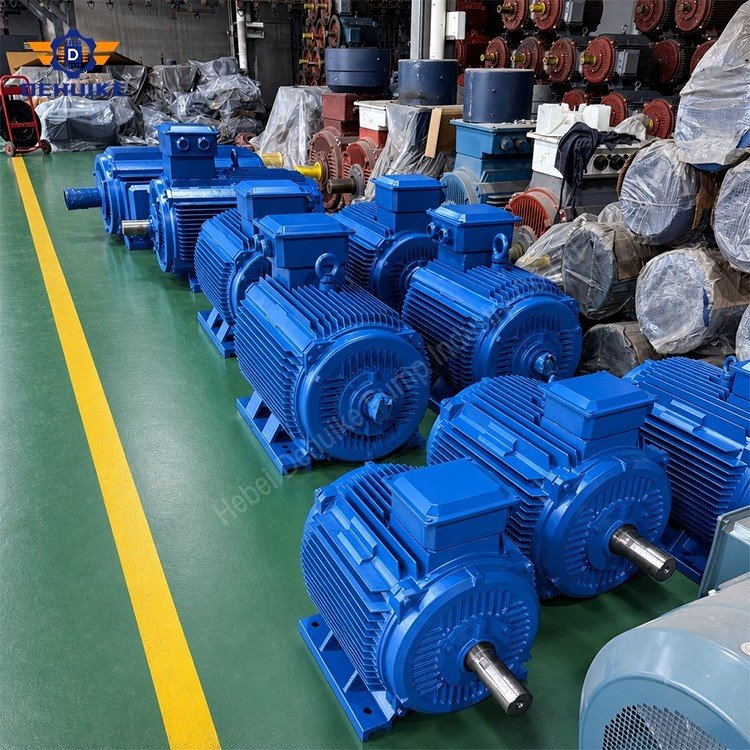
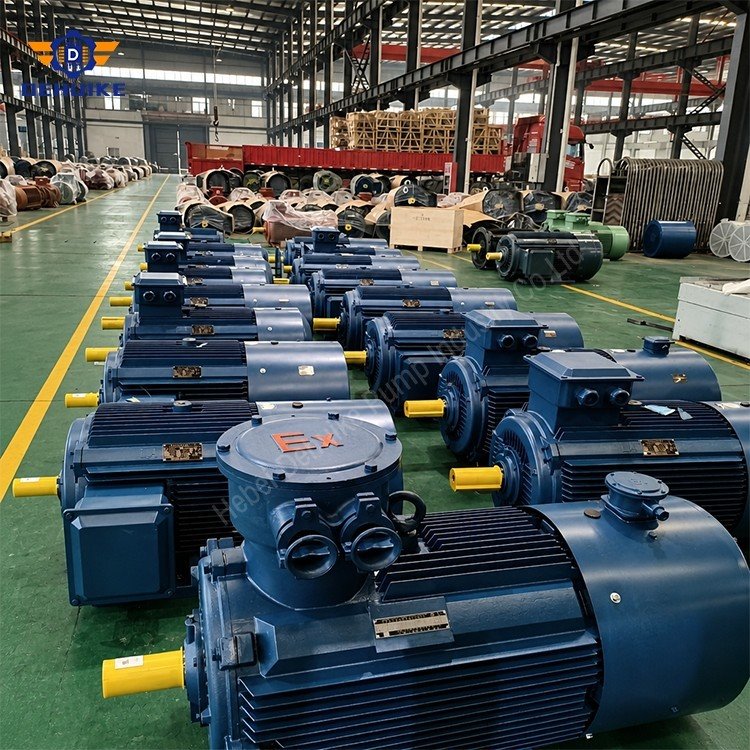
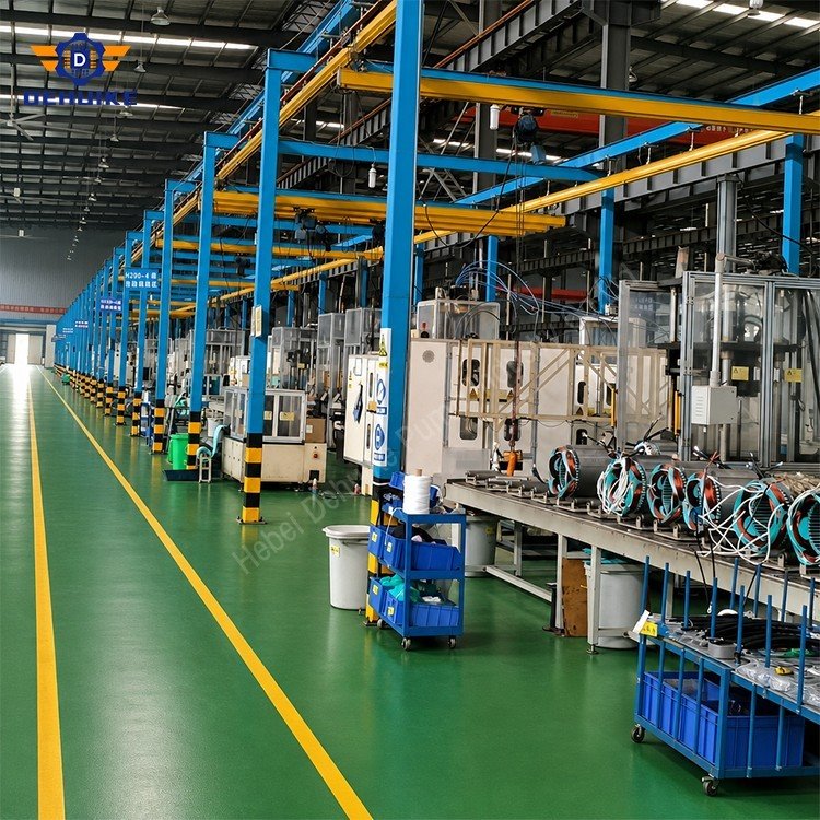
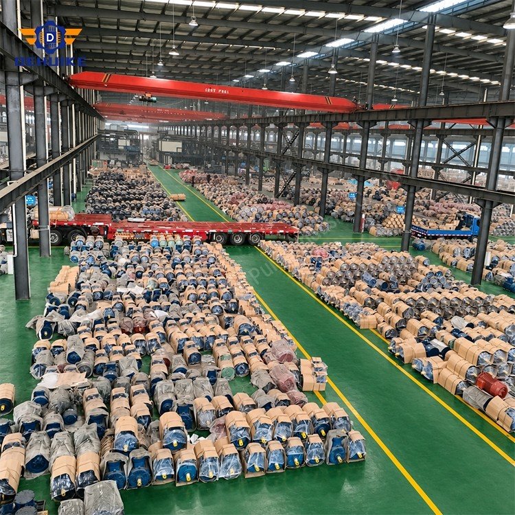
Hebei Dehuike Pump Industry Co., Ltd. is one of the most reliable manufacturers and suppliers of synchronous electric motor in China. With abundant experience, we are committed to providing high quality customized pumps with competitive price. Welcome to wholesale bulk synchronous electric motor for sale here from our factory. Also, pricelist is available.
Synchronous Electric Motor for Constant-Speed Process Drives and Power-Factor Support
A Synchronous Electric Motor is chosen when a process benefits from speed that is locked to the frequency of the electrical supply and when the interaction between the motor and the facility power system must be considered carefully. In a conventional synchronous operating condition, rotor speed follows synchronous speed determined by supply frequency and pole arrangement rather than varying with load in the same manner as an induction motor. This operating characteristic makes the motor relevant to applications where repeatable rotational speed, process coordination, and power-system behavior are important selection topics.
The motor is not a universal replacement for every industrial drive. It is a machine that should be selected around a defined operating philosophy. The driven load, required speed stability, starting sequence, available control equipment, field-excitation arrangement, mechanical train, utility conditions, and maintenance capability all need to be understood before a final configuration is confirmed.
This article is intended as a publish-ready industrial product guide without unsupported numerical claims. It does not state a fixed voltage, output range, pole count, speed, excitation system, power factor, starting current, enclosure, efficiency level, temperature rise, certification, or test scope. Those values and features must be specified in the approved technical documentation for the exact Synchronous Electric Motor configuration and project.
Understand What "Synchronous" Means in a Drive System
The word "synchronous" refers to a defined relationship between the motor's rotating field and the rotor. When the machine is operating in synchronism, the rotor turns at the synchronous speed associated with the electrical supply frequency and the selected pole arrangement. The practical advantage is speed behavior that can remain stable while the load varies within the capability of the selected motor and complete drive system.
This does not mean that load can be ignored. A process still imposes torque demand, inertia, transient events, and mechanical limitations. The motor, coupling, gearbox, driven machine, and control system need to be selected together. A synchronous machine can support an application requiring constant speed, but it cannot compensate for an incorrectly sized compressor, an unstable pump system, a damaged transmission, or a process demand outside the project design basis.
For procurement and engineering teams, the selection conversation should begin with the process requirement:
•Is a stable shaft speed central to product quality, process timing, or mechanical coordination?
•Does the load run continuously, cycle through defined states, or experience large torque swings?
•Is the machine connected directly, through a gearbox, or through another transmission system?
•Is the facility seeking a defined power-factor behavior in addition to mechanical output?
•How will the motor be started and brought into synchronism?
•Which personnel will operate, maintain, and troubleshoot the excitation and control equipment?
These questions create a meaningful foundation. They distinguish a synchronous-drive project from an ordinary motor replacement decision based solely on a broad power category.
Relate Speed Stability to the Process Requirement
Constant or tightly managed speed can matter when a process must repeat a mechanical action at a controlled rate. Examples can include compressors, pumps, blowers, mills, mixers, extruders, paper-related machinery, rolling equipment, process lines, and industrial test systems. The final suitability depends on the individual machine and operating sequence.
In a frequency-based synchronous system, speed is connected to the supply frequency and pole configuration. Where speed variation is required, the control architecture and motor design must be reviewed as a complete package. The expected speed range, torque characteristics, response requirements, cooling conditions, and control strategy all need to be confirmed in project documentation.
A stable-speed objective should be described precisely. Some buyers need a fixed rate during a long continuous process. Others need several repeatable operating points. Some installations need a motor to maintain a coordinated relationship with another machine. These cases are different and should not be represented by the same generic specification.
The motor selection becomes more reliable when the requested speed behavior is tied to observable process outcomes instead of broad phrases such as "high performance" or "heavy duty."
Examine the Rotor and Excitation Concept
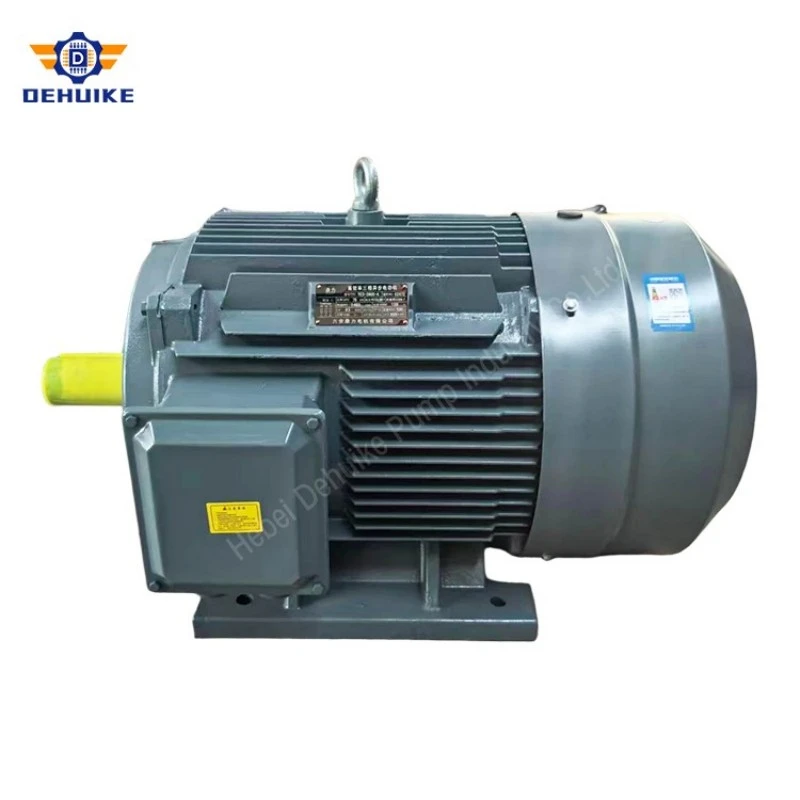
A synchronous motor uses a rotor field that interacts with the rotating magnetic field created by the stator. The final rotor and excitation arrangement depends on the selected machine design. It may involve a field system, excitation equipment, control functions, and protective monitoring appropriate to the project.
This distinction matters because the excitation system is not a peripheral accessory. It is part of the operating concept. It can influence synchronization, field control, power-factor behavior, alarm management, and the information available to operators. The motor package should therefore be reviewed as a coordinated assembly: stator, rotor, excitation method, starting arrangement, protection, instrumentation where specified, and control interface.
During the inquiry stage, buyers should identify whether the project has requirements for local operation, remote monitoring, plant automation communication, alarm indication, event records, or condition signals. These requirements should be described in the project documentation and confirmed against the final selected configuration.
The International Electrotechnical Commission's IEC 60034-1 applies broadly to rotating electrical machines, while IEC 60034-2-1 covers standard methods for determining losses and efficiency from tests and explicitly applies to AC synchronous and induction machines rated for mains operation. These documents provide a technical framework for rating and test methods, but they do not eliminate the need for a project-specific specification.
Use Power Factor as a System-Level Discussion
One reason synchronous motors are considered in certain industrial installations is their potential relationship with reactive power and power factor. The actual power-factor behavior depends on the motor design, excitation condition, operating point, and complete electrical system. It should be reviewed by qualified electrical engineers rather than presented as an automatic result for every motor application.
Power factor is relevant because industrial electrical systems include both real power used for useful work and reactive power associated with magnetic fields and network conditions. A facility may monitor power factor for utility, capacity, or system-management reasons. Where a synchronous motor is being evaluated for a process drive, its excitation strategy can be part of a wider discussion about reactive-power requirements.
This is not a reason to make unverified claims about guaranteed correction results. The network must be studied as it exists: transformer capacity, other loads, capacitor banks if present, variable-speed equipment, harmonics, utility requirements, switching events, and protection arrangements may all affect the engineering decision.
A disciplined project review separates the two questions:
1. What mechanical work must the motor deliver to the process?
2. What electrical power-system behavior is required or beneficial at the installation point?
Bringing these questions together can support a better-informed specification. It also prevents the motor from being treated as a standalone power-factor device without confirming whether it is appropriate for the actual mechanical duty.
Plan the Starting and Synchronization Sequence
Project data should describe the load at rest, rotating inertia, breakaway torque, acceleration time expectation, start frequency, process restrictions, and any requirement for controlled ramping. The starting equipment and control philosophy must be selected to support these conditions.
For a large fan, pump, compressor, mill, or process machine, the start may be connected to valves, dampers, unloaders, clutches, or other machine features. These elements can affect the torque seen by the motor during the starting sequence. The motor inquiry should include the connected equipment behavior rather than treating the motor as isolated from the process.
The synchronization arrangement should also be clear in the operating description. The system may need defined permissives, readiness checks, field-control actions, and protective logic. The exact scheme is project-specific. Operators and maintainers should receive documentation that explains the normal sequence, expected indications, alarm states, and conditions that prevent a start.
|
Sequence Stage |
Information Needed for Engineering Review |
|
Pre-start condition |
Machine status, lubrication or auxiliary requirements, valves or dampers, and permissive signals. |
|
Acceleration |
Inertia, load torque, required ramp behavior, and limits from the supply or mechanical train. |
|
Synchronization |
Field-control concept, control interface, confirmation signals, and sequence responsibility. |
|
Normal running |
Expected load range, speed requirement, power-system considerations, and process controls. |
|
Shutdown |
Normal stop sequence, coast-down or controlled stop needs, and process isolation requirements. |
|
Restart after trip |
Required inspection, reset authority, and conditions that must be verified before return to service. |
Clear sequence definition reduces the risk of a motor package being technically capable but operationally unclear at the plant.
Integrate the Motor With the Driven Train
The mechanical side of a synchronous motor project requires the same discipline as the electrical side. The motor shaft, coupling, baseplate, gearbox, and driven machine need to form an aligned and serviceable train. A process requirement for constant speed does not remove the need for correct mechanical interface design.
Direct-coupled equipment should be reviewed for shaft dimensions, coupling type, allowable movement, foundation arrangement, alignment procedure, and access for inspection. Gear-reduced equipment adds another layer: gear ratio, input connection, torsional considerations where relevant, lubrication system, and support structure must be coordinated with the motor application.
Some processes include a high-inertia rotating mass. The acceleration requirement and torsional behavior should be addressed through the project engineering process. Do not infer acceptable starting performance or shaft-train capability from a motor name alone. The machine supplier and motor engineering team need compatible data for the final selection.
Site layout should also allow proper maintenance. Motor removal, coupling inspection, electrical connection access, cooling clearance, and excitation-system access should be considered in the installation plan. A large or strategically important drive is difficult to maintain if its service route is blocked by permanent pipework, platforms, or adjacent machinery.
Apply Synchronous Drives to Stable Process Equipment
Synchronous motors are often considered for demanding industrial drive duties, but the application must be confirmed for the actual process. The following examples show how the evaluation may differ across equipment types.
Compressors and Gas-Handling Equipment
Compression systems can require stable rotational behavior, substantial starting coordination, and close interaction with process controls. The review should include compressor type, operating sequence, unloading arrangement, process pressure condition, train inertia, coupling design, and the consequences of an interruption. If power factor is part of the project objective, it should be evaluated with the facility electrical study rather than assumed from the motor category.
Large Pumps and Water-Process Facilities
Pumping systems may be part of transfer, circulation, cooling, irrigation, water-treatment, or process-fluid networks. A synchronous-drive review should connect the motor to pump curves, hydraulic system conditions, starting position, valve sequence, pipework behavior, and any requirement for stable rotational speed. The final motor selection should follow the confirmed pump and site data.
Mills, Mixers, and Material Processing Machines
Grinding, milling, mixing, agitation, and related process machines can have significant inertia and changing torque demand. The equipment review should cover material characteristics, loading sequence, gearbox or direct-drive arrangement, start-up conditions, production cycle, and mechanical protection. The motor and process controls need a shared operating concept.
Air Systems and Large Blowers
Blowers, fans, and air-process equipment can be sensitive to damper position, duct condition, operating point, and start sequence. The motor should be selected with the impeller or blower characteristics, system resistance, isolation arrangements, process interlocks, and maintenance route in mind.
Test Rigs and Coordinated Production Machinery
Some machinery requires repeatable shaft behavior because it is linked to test conditions, timing systems, or another mechanical section. These projects should state the coordination requirement clearly, including any control interface, reference signal, speed-management need, and sequence conditions.
Protect the Motor, Field System, and Process
A synchronous-drive protection philosophy must address the complete machine package and process responsibility. The required protection functions are determined by the final motor design, excitation system, control architecture, electrical network, applicable standards, and project risk assessment.
Protection and monitoring may relate to the motor circuit, excitation arrangement, operating state, temperature indication where specified, bearing-related information where specified, vibration monitoring where specified, process permissives, or control-system alarms. The exact functions should be listed in the approved technical documentation rather than inferred from a generic article.
The key principle is coordination. A protective action may indicate an electrical condition, an excitation condition, a mechanical concern, or a process interlock. Operators need enough information to distinguish these categories. A reset should not replace investigation when the system indicates an abnormal condition.
A well-prepared control narrative can include:
•Normal start prerequisites and operator permissions.
•The expected transition from start to synchronized running.
•Alarm categories and their intended meaning.
•Trip conditions that require inspection before restart.
•Process conditions that command a normal stop rather than a protection trip.
•Responsibility boundaries between the motor supplier, panel builder, machine supplier, contractor, and plant operator.
This documentation helps turn a sophisticated drive package into an operable plant asset.
Commission the Drive as a Coordinated System
Commissioning should confirm the integrated behavior of motor, excitation, controls, supply, and machine. It is not limited to proving that the shaft turns. A successful commissioning plan defines what must be checked before energization, which conditions must be observed during the first sequence, and what records will be retained for future operation.
Before start-up, qualified teams should review the approved drawings, connection information, mechanical installation, coupling condition, auxiliary systems, control interfaces, safety arrangements, and access clearances. The actual checks and test procedures must be appropriate to the selected equipment and site rules.
During controlled commissioning, observe the start sequence, acceleration behavior, transition to synchronous operation, process response, control indications, and any protective or alarm messages. The commissioning record should preserve the approved configuration and relevant baseline information without creating unsupported claims about performance outside the tested project condition.
After handover, the operating team should have access to the motor data, control narrative, drawings, alarm list, maintenance requirements, and clearly defined escalation path. This is particularly important where field control and process control are coordinated by more than one party.
Maintain Excitation and Mechanical Health
Routine maintenance should respect the fact that a synchronous motor package includes both electrical and mechanical elements. The maintenance program should follow the product documentation and site procedures, with tasks adapted to operating criticality, environment, and installed accessories.
Mechanical checks can include the condition of the coupling, mounting, cooling path, foundation, guards, and the surrounding machine. Electrical and control checks may include inspection of accessible terminals, panel records, control indications, and excitation-related equipment where applicable. Specialized testing or adjustment should be performed only by qualified personnel using approved procedures.
Trend information is useful when interpreted against the actual installation. Changes in vibration, temperature behavior, operating sound, start sequence, alarm history, or process response can indicate that further review is needed. They do not automatically identify a single cause. A structured investigation should consider the motor, field system, supply, driven machine, and process condition.
Good records are especially valuable for major drives. Keep current copies of the approved data sheet, drawings, excitation information, control settings where authorized, commissioning records, service history, and changes made to the driven equipment. These documents support planned maintenance and reduce uncertainty when troubleshooting or arranging a replacement.
Create a Project-Ready Technical Inquiry
A high-quality inquiry for a synchronous motor should explain the desired process outcome as well as the electrical and mechanical interfaces. The information below helps organize that request.
|
Inquiry Category |
Project Information to Provide |
|
Process duty |
Driven equipment, required operating speed behavior, load profile, operating schedule, and process importance. |
|
Mechanical train |
Direct coupling or gearbox arrangement, inertia information, shaft interface, base layout, and service access. |
|
Electrical supply |
Site voltage, frequency, phase arrangement, network constraints, and connection point. |
|
Starting concept |
Expected start conditions, acceleration requirement, process permissives, and control responsibility. |
|
Excitation and control |
Required local/remote functions, automation interface, indications, alarms, and monitoring expectations. |
|
Power-system objective |
Any confirmed requirement for power-factor or reactive-power evaluation at the facility. |
|
Environment |
Indoor/outdoor location, cooling conditions, contamination, ambient exposure, and maintenance access. |
|
Documentation |
Requested drawings, test records, tagging, packing, shipment, inspection, and destination-market requirements. |
This information gives the engineering team a basis for evaluating a final configuration. It also keeps unconfirmed assumptions visible before production and commissioning.
Frequently Asked Questions
Q: What is a Synchronous Electric Motor used for?
A: It is used where a process benefits from rotational speed linked to the electrical supply frequency and where the motor's relationship with the power system may be relevant. Typical evaluations can include compressors, pumps, blowers, mills, mixers, and coordinated industrial machinery, subject to project-specific confirmation.
Q: Does a synchronous motor always run at exactly the same speed?
A: In normal synchronous operation, rotor speed is tied to supply frequency and pole arrangement. Actual system behavior must still be reviewed with the motor design, control strategy, load capability, and operating conditions for the project.
Q: Why is excitation important?
A: The excitation arrangement is part of the motor's operating concept. It supports the rotor-field condition required for synchronous operation and may be relevant to synchronization, control, monitoring, and power-factor behavior. The actual arrangement must be confirmed for the supplied motor.
Q: Can a synchronous motor improve power factor?
A: Its excitation condition can be relevant to reactive-power and power-factor behavior, but the effect depends on the selected machine, operating point, excitation system, and facility electrical network. A project electrical study should define any required objective rather than assuming a fixed outcome.
Q: How does a synchronous motor start?
A: The starting and synchronization sequence is specific to the motor and project control system. It should be defined from the connected load, inertia, supply conditions, excitation arrangement, and operating procedure.
Q: What information is needed for a compressor or pump application?
A: Provide the machine type, duty data, start condition, process sequence, mechanical train, supply details, control philosophy, environmental conditions, and any power-system requirements. The final motor package should be reviewed against the complete application.
Q: Can a synchronous motor be used with speed control?
A: A control-based speed requirement must be assessed with the motor design, converter or control architecture where relevant, operating range, load characteristics, and cooling conditions. Confirm the complete system before order approval.
Q: Are specific ratings or certifications included on this page?
A: No. The article does not make unverified rating or certification claims. The approved technical schedule for the ordered configuration must define the applicable electrical, mechanical, environmental, testing, and compliance information.

Hot Tags: synchronous electric motor, China synchronous electric motor manufacturers, suppliers, factory