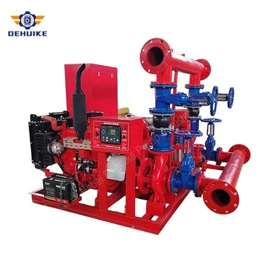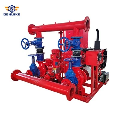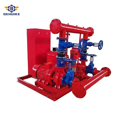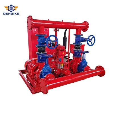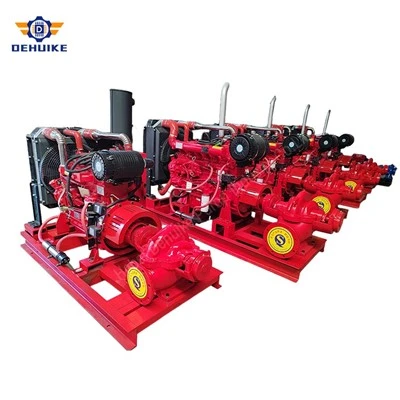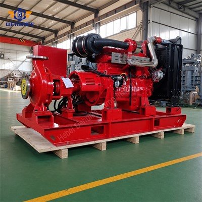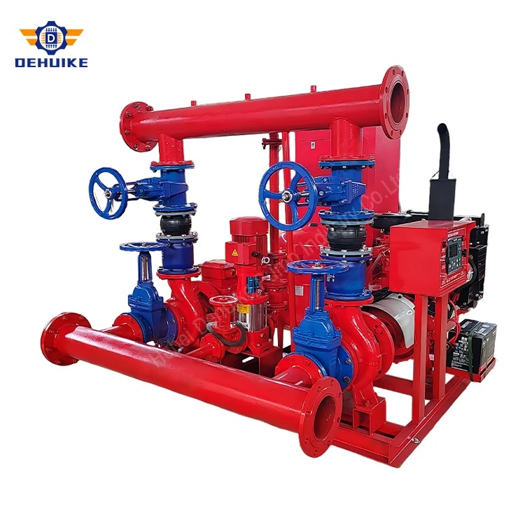
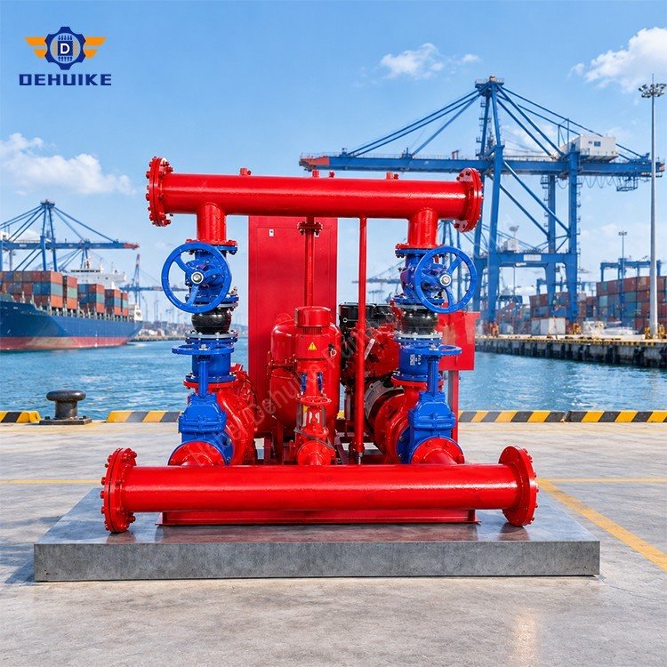
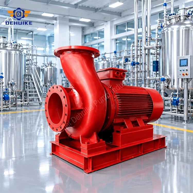
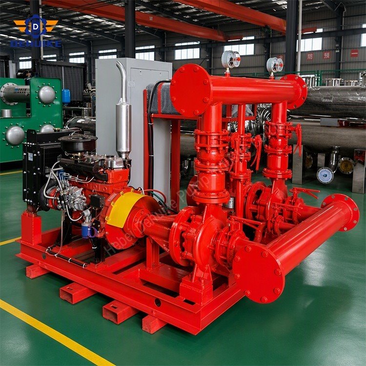
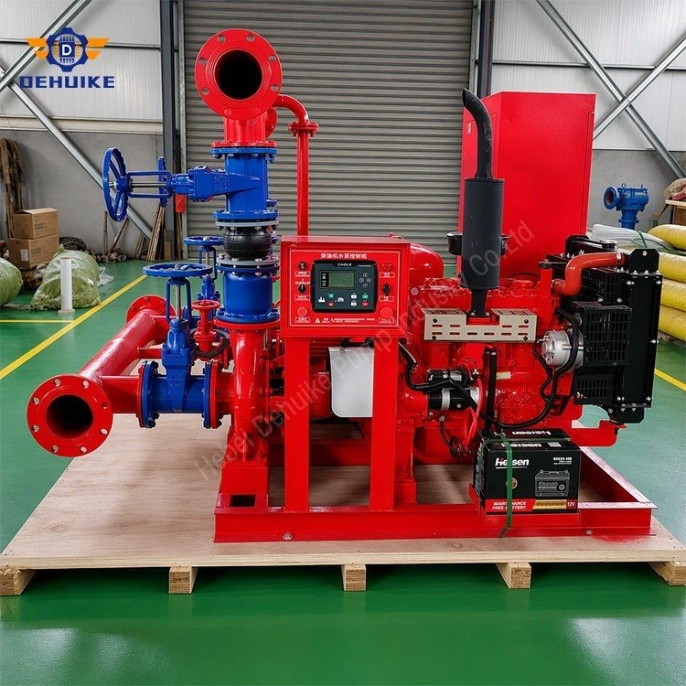
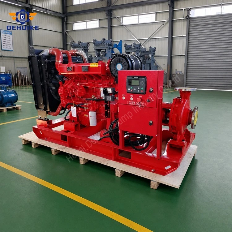
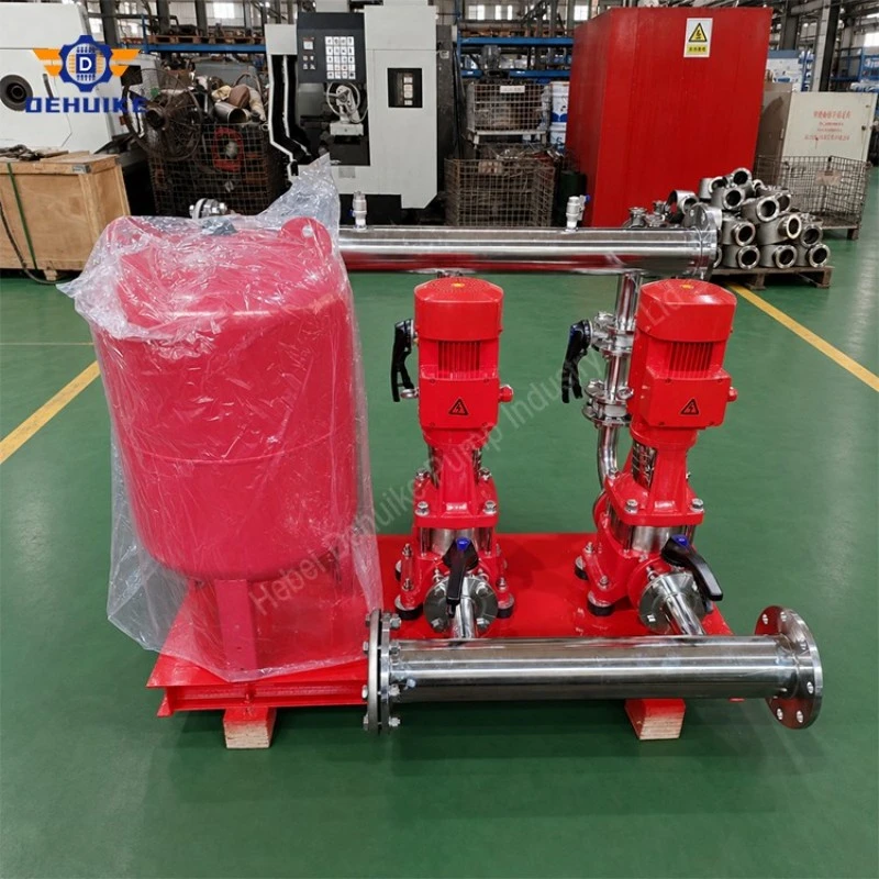
Hebei Dehuike Pump Industry Co., Ltd. is one of the most reliable manufacturers and suppliers of fire hydrant pump set in China. With abundant experience, we are committed to providing high quality customized pumps with competitive price. Welcome to wholesale bulk fire hydrant pump set for sale here from our factory. Also, pricelist is available.
Fire Hydrant Pump Set for Reliable Building and Industrial Fire Water Supply
Every fire pump set is accepted on a flow test that runs well beyond its rated duty - typically to 150 per cent of the rated flow. The pump is expected to hold a substantial fraction of its rated pressure out there, and the driver is expected to carry the load without tripping. When a set fails that test, the first instinct is to blame the pump or the engine. Most of the time the machine is doing exactly what its curve says, and the suction arrangement behind it is already at its limit.
The reason is arithmetic. Friction in the suction pipe rises with the square of the flow, so the flow at 150 per cent costs 2.25 times the friction head it cost at rated duty. On a suction line sized to look reasonable at the duty point, that head has to come from somewhere, and the only thing available is the margin between the water level and the pump inlet. Fire pumps have very little of that margin to spare, because the water comes from a tank at atmospheric pressure and the tank is emptying while the pump runs.
The margin is set by the lowest water level, not the normal one
A fire pump drawing from a dedicated tank has an available NPSH equal to the height of the water surface above the pump inlet, minus the losses in the suction line and fittings, minus a margin for the vapour pressure of the water. At the start of a fire the tank is full and that height is generous. At the end of a fire, when the tank is down to its residual level, it is not - and that is the condition the pump has to survive, because a fire can last long enough for the level to fall.
So the number that matters to the designer is the low-water level, not the normal level, and the losses that matter are the ones at 150 per cent flow, not at the rated point. Both of those figures are usually worse than the ones written on the pump schedule. The pump schedule says rated flow and a pressure; the tank drawing says normal level; the suction pipe details are often left to the installer.
The practical check is simple and rarely done early enough: take the low-water level, subtract the suction losses at 150 per cent flow, and compare the result with the pump's NPSH requirement at that flow. If the answer is negative, no pump selection will fix it; the tank has to be higher, the pump lower, or the suction line larger.
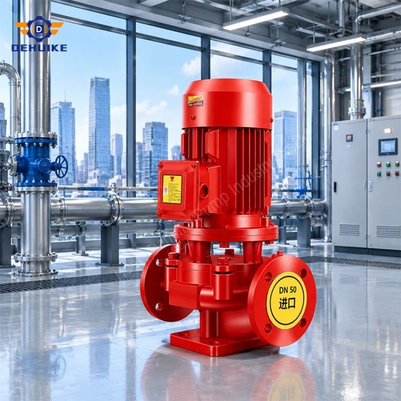
Vortexing appears exactly at the flow that matters
A suction intake in a tank does not fail gradually. Below a certain flow the water approaches the bell mouth and turns into the pipe quietly. Above it, a vortex forms on the surface, and when the core of that vortex reaches the intake, air enters the pump. The flow at which this happens depends on submergence - the depth of water above the intake - and on intake velocity, which is highest at the moment the pump is asked for the most water.
This is why a fire pump set can pass a duty-point test and fail the overload test on the same tank: the extra flow is what tips the intake into vortexing. The pump then loses head, the flow falls, the vortex collapses, the pump recovers, and the test reading oscillates in a way that looks like a control fault rather than a hydraulic one.
The countermeasures are geometric. Keep the intake well below the low-water level rather than just below the normal level. Use a bell mouth or a flared entry so that the approach velocity is low. Provide an anti-vortex plate or a baffle where the tank geometry encourages rotation. Keep the intake away from the tank wall and off the floor, so that it draws from open water rather than from a corner. None of these are expensive, and all of them are decided before the tank is cast.
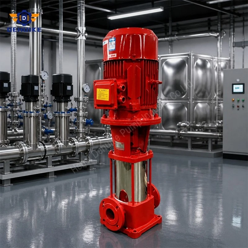
The suction line at 150 per cent
Suction piping for a fire pump is often sized by the same rules as the discharge, which is a mistake. The discharge can afford velocity; the suction cannot, because every metre per second of velocity costs head that the pump needs. On a pump delivering 80 L/s at its rating, the overload point is 120 L/s, and a suction line chosen for the rated flow will be carrying a third more water at the moment of the test.
Three details cause most of the avoidable loss. An eccentric reducer placed flat instead of with the taper on the bottom traps air at the top of the pipe. An elbow immediately at the pump flange leaves a swirl that reduces the effective area of the impeller eye. And a strainer, added for good reasons at commissioning, is seldom checked for its own pressure drop at 150 per cent - a partly blocked strainer at that flow is a suction problem that looks like a pump problem.
The gauge that settles arguments is a compound gauge at the pump suction flange, read during the overload test. If the reading is close to the vapour pressure of the water, or is visibly fluctuating, the suction is the constraint regardless of what the discharge side says. If the suction reading is healthy and the pump still will not make its pressure, the problem has moved inside the machine.
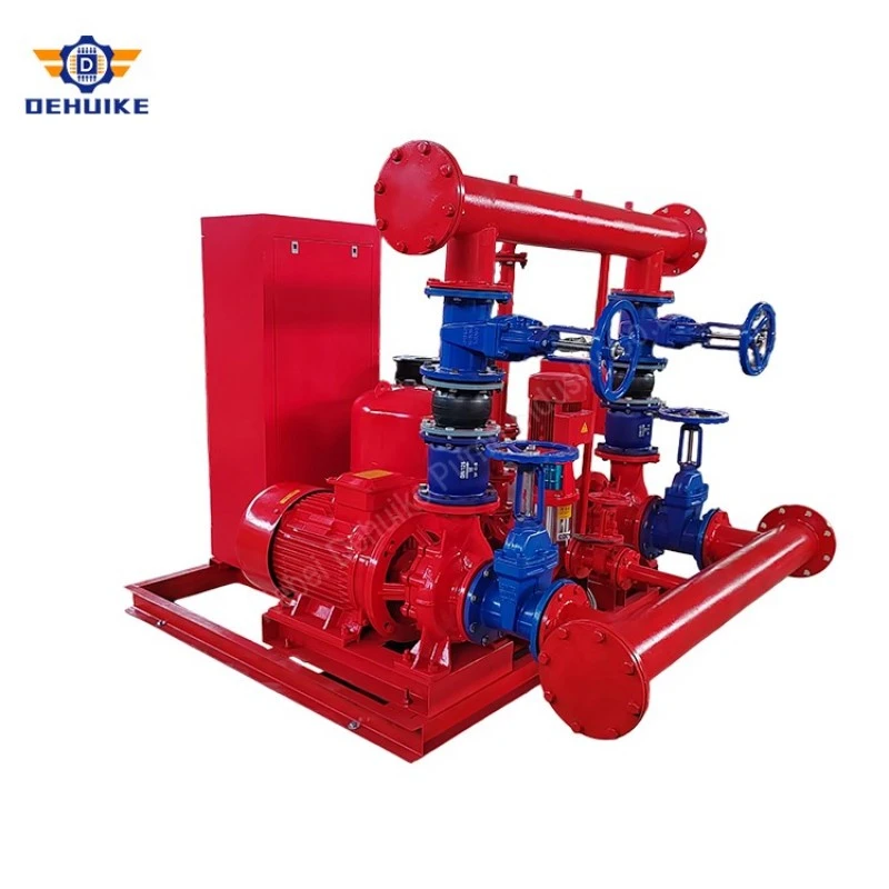
Table 1 The three points on a fire pump acceptance test
|
Test point |
What it proves |
What it can hide |
|
Churn, zero flow |
Shutoff pressure; driver and controller response |
Casing heats quickly; not a capacity proof |
|
Rated flow |
The duty the system was designed around |
Little about the suction line at higher flow |
|
Overload, 150% flow |
Capacity margin and suction adequacy together |
Fails for suction reasons and looks like pump failure |
Churn is a pressure test, not a capacity test
The first point on any fire pump test is shutoff, and it is worth being clear about what it demonstrates. At zero flow the pump develops its maximum head, which confirms the pressure capability and exercises the controller and the driver. It proves nothing about capacity. It is also the condition that heats the machine fastest, because all of the absorbed power is going into the water trapped in the casing, with no flow to carry it away.
For an electric set, churn is a short event and the motor does not mind. For a diesel set it is a different matter: the engine is at full governed speed with almost no load, the casing temperature climbs, and a long churn test with the engine hunting is the worst condition the set will see outside a fire. The test should be timed, not open-ended, and the water temperature in the casing should be watched rather than assumed.
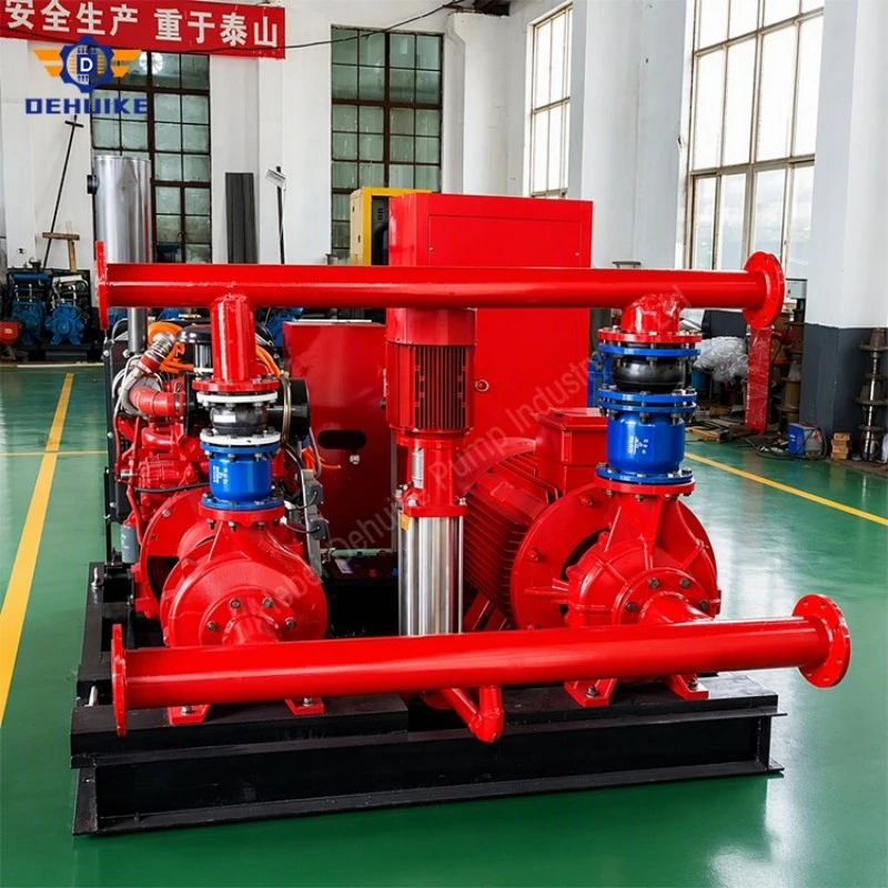
Laying out the overload test so that it is valid
The overload test needs somewhere for the water to go. Practically, that means a test header with metering valves and nozzles, or a flowmeter in the discharge, plus a drain or a recirculation route that can take the full test flow without backing up. Where the disposal capacity is short, the test gets run with valves partly closed, the flow never reaches the intended point, and the report shows a set that "passed" without ever being asked the question.
Measurement matters as much as capacity. Nozzle pressure on a test header converts to flow through a known relationship, and that relationship only holds if the nozzle is the stated size, unobstructed and at the correct pressure. A flowmeter needs its straight runs. A test that relies on a pump-mounted gauge and an estimate is a record that cannot be defended if the authority having jurisdiction asks a question later.
There is also a sequence point that gets overlooked. The suction valve has to be fully open and the tank has to be at a level that will still be adequate at the end of the test, otherwise the set is being tested against a falling margin. Running the overload test with the tank near its low-water mark is a legitimate worst case, and a useful one, but it should be a deliberate test rather than an accident of scheduling.
When the test fails, the order of diagnosis
Start at the suction gauge and work forwards. A low or fluctuating suction reading at 150 per cent points to the suction line, the intake or the tank level, and the remedy is civil or piping work, not a new pump. A healthy suction reading with a discharge pressure below the curve points to the pump: worn impeller, wrong trim, wrong speed, or a discharge-side restriction that is being read as pump shortfall. A healthy suction and a correct pressure with the driver tripping points to the electrical or engine side - protection settings, voltage drop, fuel supply, or an engine that is not delivering its rated output at the site temperature.
The most common single finding in a failed overload test, in practice, is a suction line that was sized for the duty and a tank intake that was set just below normal level. Both are decisions made early, both are cheap to get right, and neither appears on the pump datasheet that the buyer compares between suppliers.

Suction faults and how they announce themselves
|
Fault |
Signature during the test |
Fix |
|
Suction line undersized |
Flow stalls short of the target; suction gauge low |
Increase line size; reduce fittings |
|
Intake too near the surface |
Fluctuating flow and pressure; noise at high flow |
Lower the intake or raise the low-water level |
|
No anti-vortex provision |
Air entrainment, head collapse, recovery cycle |
Bell mouth and anti-vortex plate |
|
Blocked or undersized strainer |
Suction loss that grows with flow |
Clean and resize; check drop at 150% |
|
Air trapped at a flat reducer |
Rattle at start; head lower than curve |
Eccentric reducer with taper at the bottom |
FAQ: Fire Hydrant Pump Set
1. Is a flooded suction required, or can a fire pump lift from a tank?
A fire pump drawing from a tank is normally installed with the impeller below the low-water level, so the water arrives by gravity. Lifting invites air and loses the margin exactly when the flow is highest. Where a lift is unavoidable, the suction arrangement has to be designed for it, not inherited from a standard detail.
2. How much margin above the pump requirement is sensible?
Enough to cover the 150 per cent flow condition, a fouled strainer and a tank at its low-water mark, with something left over. The pump's requirement at that flow is the starting point, not the answer, and the figures should come from the pump data rather than a rule of thumb.
3. Does a vertical pump change the suction rules?
It changes the geometry, not the principle. A vertical set puts the first impeller low in the pump, which is convenient in a shallow sum, but the intake in the tank still needs submergence and the line still needs to be sized at the overload flow.
4. Can the overload test be run from the public main instead of the tank?
Only if the main can supply that flow at the required pressure without dropping below the pump's requirement. On most sites the main cannot, which is precisely why the tank exists. A test that draws from the main proves something different from a test that draws from the tank

Inquiry Call to Action
If your project requires a Fire Hydrant Pump Set for building protection, factory safety, municipal infrastructure or industrial emergency water supply, send the required flow, head or pressure, pump room layout, water source condition and quantity. The technical team can review the suitable pump structure and provide a focused fire pump set proposal.
Clear project information helps shorten selection time and improve quotation accuracy. Share your drawings, specifications and hydrant system requirements to receive a pump solution matched to your fire protection water supply needs.
Hot Tags: fire hydrant pump set, China fire hydrant pump set manufacturers, suppliers, factory