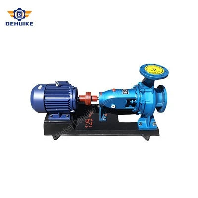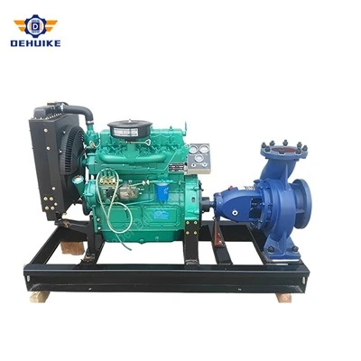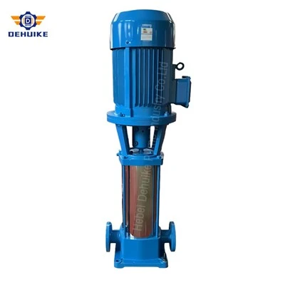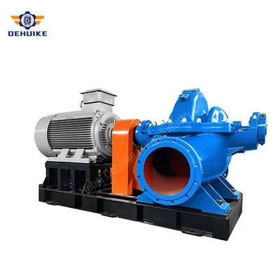
Hebei Dehuike Pump Industry Co., Ltd. is one of the most reliable manufacturers and suppliers of industrial multistage water pump in China. With abundant experience, we are committed to providing high quality customized pumps with competitive price. Welcome to wholesale bulk industrial multistage water pump for sale here from our factory. Also, pricelist is available.
Industrial Multistage Water Pump for High-Lift Clean Water Service
A boiler feed pump is bought on two numbers, flow and head, and installed around a third, temperature. The first two decide the model; the third decides whether the model survives. Feed water comes out of a deaerator at 105 °C or above, at the pressure of its own vapour, which means the pump is being asked to handle a liquid that is already at the point of boiling. Every difficulty in this application follows from that single fact.
The DG range that serves this duty covers 36 to 155 m³/h at heads from 350 to 886 m, in seven to ten stages, with NPSH requirements between 2.8 and 4.8 m at the rated point. Those figures look modest. What makes them demanding is that the available suction margin is measured against a liquid whose vapour pressure is close to the pressure in the tank.
Define the Water Transfer Requirement Clearly
On a cold-water duty, a pump can lift water from a sum because atmospheric pressure stands behind the liquid and the vapour pressure is negligible. In a deaerator the liquid is held at saturation: the pressure above it exists only because the water is at that temperature, and the moment the pressure falls, the water boils. The available NPSH is therefore not atmospheric pressure minus vapour pressure, but the elevation of the water surface above the pump inlet, minus the losses in the downcomer.
That is why deaerators stand on a structure five to eight metres above the pump floor, and why that height is designed before the pump is ordered. At 105 °C the vapour pressure is roughly 0.12 MPa absolute, at 120 °C about 0.20 MPa, and at 130 °C about 0.27 MPa. A feed pump requiring 4 m of NPSH with a metre of line loss needs a tank surface around five metres above its inlet, and on a hot day, or with a fouled strainer in the downcomer, that margin is the whole difference between a quiet pump and a cavitating one.
Two habits cause trouble here. The first is treating the deaerator as a tank that can be lowered to suit the building. The second is sizing the downcomer on velocity alone: a line that is one size too small costs more in friction than the elevation can afford, and the pump inlet then sees a pressure below the vapour pressure of the water it is being fed.
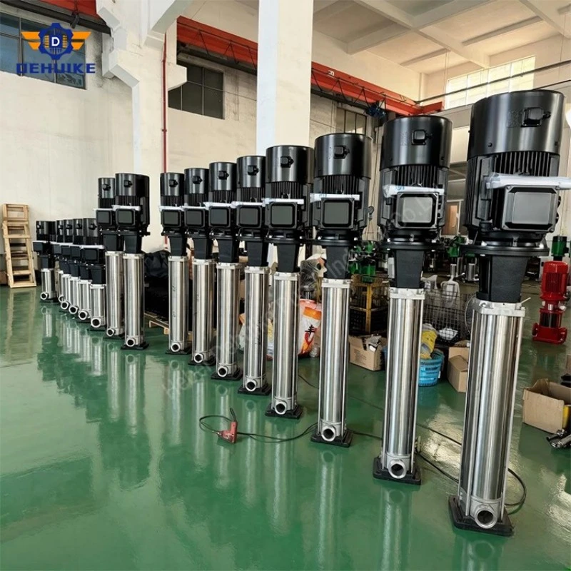
Cavitation in feed water looks different
Cavitation in a cold-water pump is usually heard before it is seen: a rattle, then a falling head. In feed water the bubbles form and collapse in a liquid close to saturation, and the damage is concentrated on the first-stage impeller inlet, where the pressure is lowest. The signature is erosion of the blade leading edges and a slow loss of head that looks like wear ring clearance until the pump is opened.
The first stage is the vulnerable one because every later stage works at a higher pressure. The NPSH requirement quoted for the pump is therefore essentially the requirement of the first impeller, measured at the rated flow. At lower flow the requirement rises, and this is the trap in a plant that runs its feed pump at part load for long periods: the datasheet margin was proven at rated flow, while the pump spends its life at half of it, where the incidence angles at the inlet are wrong and the cavitation margin is thinner than the table suggests.
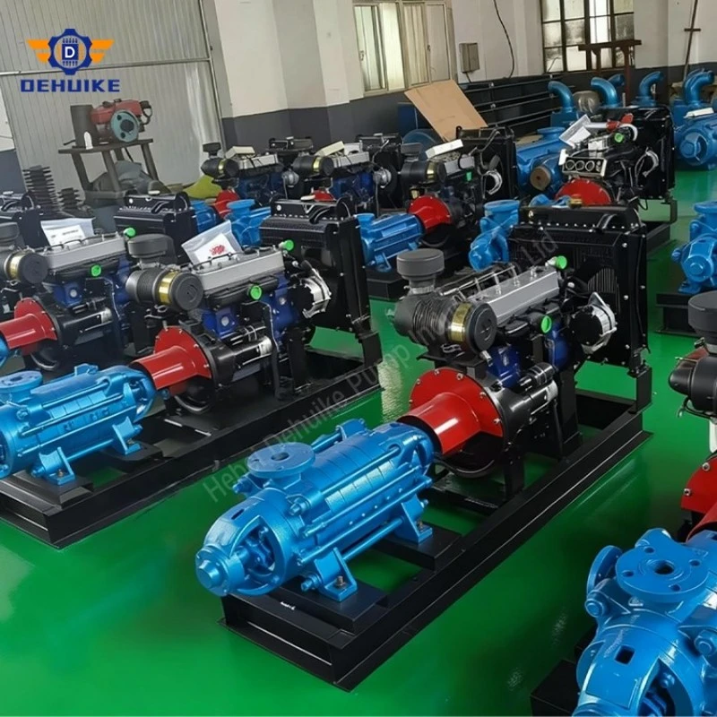
The seal sits in the hottest, thinnest place
A mechanical seal on a feed pump has to run in water at 105 to 160 °C, at the suction pressure of the first stage or the interstage pressure depending on where the seal chamber is taken. At those temperatures the thin film between the faces is close to flashing, and any local heat generation is enough to break it. That is why feed pump seals are balanced cartridges with a cooled or quenched chamber rather than a standard seal in a standard box.
What the quench does is keep the chamber below the flashing point of the water and remove the heat that friction adds. Where the quench is a cool condensate or a closed loop with a cooler, the flow matters more than the pressure: a trickle that does not move heat is worse than useless, because it looks like protection and is not. On commissioning, the flow at the seal is a measurement, not an assumption.
The seal faces themselves are chosen for hot water rather than for chemical resistance: a hard face against a carbon or silicon carbide face, with the spring and elastomer materials rated for the temperature. A seal that is correct for cold water and installed in a 130 °C chamber fails within weeks, and the failure is usually reported as a pump problem.
Minimum flow is a temperature limit, not a hydraulic one
Water already at saturation needs only a fraction of a degree of heating to begin to vaporise. A feed pump running at low flow converts a large shaft power into a small flow, and the difference becomes heat in the water inside the casing. On a 500 m, 100 kW machine at 46 m³/h, the temperature rise per pass at rated flow is under a kelvin; at a quarter of the flow, with the same head, the water is being heated several times faster, and the margin to boiling is gone.
This is the reason feed pumps are fitted with a minimum-flow recirculation line back to the deaerator, usually through a three-way valve that opens the line before the discharge valve closes. It is not there to protect the pump from low flow in the abstract; it is there because the pump would otherwise boil its own contents. The line has to be sized for the heat, not for a nominal percentage, and it has to be open whenever the boiler demand falls below the threshold - including during start-up, when the discharge is still shut.
Boiler houses also need the opposite guard: a non-return valve on the discharge, so that drum pressure cannot push hot water backwards through a stopped pump. Backflow through a stationary machine is a thermal shock on the casing, the seal and the rotor, and it is the reason the discharge check valve is treated as a safety item rather than a plumbing detail.
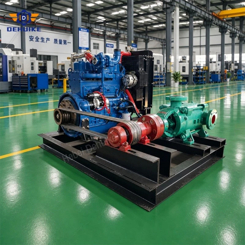
Table 1 DG boiler feed ratings, and the suction margin they demand
|
Model |
Flow (m³/h) |
Total head (m) |
Stages |
NPSHr (m) |
Efficiency |
Shaft power (kW) |
|
DG36-50x7 |
36 |
350 |
7 |
3.0 |
60% |
57.2 |
|
DG46-50x10 |
46 |
500 |
10 |
2.8 |
63% |
100.0 |
|
DG85-45x8 |
85 |
360 |
8 |
4.5 |
72% |
115.8 |
|
DG85-67x10 |
85 |
670 |
10 |
4.0 |
65% |
238.5 |
|
DG155-67x8 |
155 |
536 |
8 |
4.5 |
74% |
305.6 |
|
DG150-100x9 |
150 |
886 |
9 |
4.8 |
70% |
517.5 |
Heat moves the machine, and start-up is the riskiest hour
A cold feed pump and a hot one are not the same shape. The casing grows as it reaches temperature, the tie rods that clamp the stage stack grow with it, and the rotor, which is a solid shaft with impellers along its length, grows differently from the casing around it. That is why the cold alignment includes an offset and why the axial clearance in a feed pump is checked hot as well as cold.
Start-up is where this matters most. Bringing a cold pump onto 130 °C water in a few minutes produces a thermal gradient along the stack that the clearances were never dimensioned for, and the wear rings are what absorb it. The practices that avoid it are unglamorous: warm the pump through with a small flow before loading it, bring the discharge up gradually, and do not let the machine stand full of hot water with no flow through it.
The other start-up hazard is the discharge valve. A feed pump started against a closed discharge with the recirculation line closed has no path for its energy, and the water in the casing heats within minutes. Any control logic that could produce that sequence - a three-way valve that travels the wrong way, a minimum-flow line isolated for maintenance and not reopened - is a pump failure waiting for a busy shift.
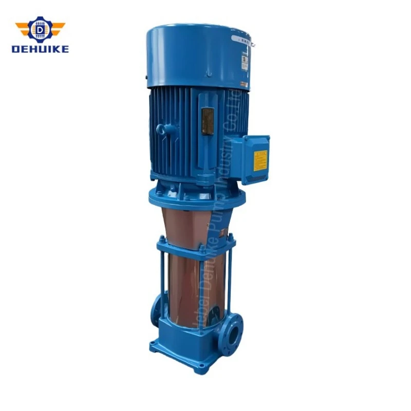
Control, standby, and the second machine
Feed water control normally works on drum level, with the pump delivering into a control valve or a variable-speed drive. Both arrangements need the same guard: the pump must never operate below its minimum flow, and the control must know that. A three-way valve that recirculates while throttling to the boiler is the common solution on constant-speed machines; a variable-speed drive achieves the same result only if the minimum speed is set high enough to keep the recirculation open.
Standby pumps bring their own risk. An automatic start on low drum level puts a cold or warm machine into service within seconds, and the discharge check valve, the warm-through line and the seal quench all have to be in a state that allows it. A standby pump that has been isolated from its quench, or whose suction valve has been left closed after maintenance, will start into a dry or hot condition and fail in a way that looks like a control fault.
This is also where the second machine earns its place in the selection. Two pumps each capable of the full duty, with one on standby, is the normal arrangement; two pumps each sized at half duty, running in parallel, gives no standby at all unless a third machine exists. The distinction is not about redundancy in the abstract, but about what happens on the night the running pump seals fail.
Table 2 Four temperature-driven requirements, and what they become in hardware
|
Requirement |
Because the water is at saturation |
What it becomes on site |
|
Suction margin |
Vapour pressure rises with temperature |
Deaerator elevated; downcomer sized for low loss |
|
First-stage margin |
NPSHr rises away from rated flow |
Operating range checked, not just the duty point |
|
Seal environment |
Face film close to flashing |
Balanced cartridge seal with cooled or quenched chamber |
|
Minimum flow |
Heat input raises the water to boiling |
Recirculation line to the deaerator, open before the discharge closes |
Frequently Asked Questions
Q: Can the pump draw from a tank at atmospheric pressure instead of a deaerator?
A: It can, and the suction problem disappears because the water is below its boiling point. What changes is the thermal duty on the boiler and the oxygen content of the feed water, which is why deaerators are used. The pump selection then follows ordinary cold-water rules rather than the ones described here.
Q: Why does the pump lose head gradually rather than suddenly?
A: Because the usual cause is wear ring clearance opening across the stages, helped by cavitation erosion at the first-stage inlet. The loss is progressive and easy to mistake for a boiler-side change. Compare the head at a measured flow with the commissioning figure before opening the machine.
Q: Is a variable-speed drive enough to protect a feed pump at low flow?
A: Only if the minimum speed and the recirculation arrangement are set so that flow never falls below the pump's minimum. A drive that can slow the pump to a trickle has removed the hydraulic problem and left the thermal one in place.
Q: How much elevation above the pump should the deaerator have?
A: Enough to cover the pump's NPSHr at the flow it will actually run, plus the downcomer losses, plus a margin for a fouled strainer and a hot day. It is a plant design decision made with the pump's data, not a standard dimension.

Hot Tags: industrial multistage water pump, China industrial multistage water pump manufacturers, suppliers, factory