

Slurry pumps are designed to transport mixtures of solid particles (slurry) and water. In terms of operating principle, they are a type of centrifugal pump. In the steel industry, they are primarily used to transport sludge in systems such as converter dust-removal water, blast furnace gas-scrubbing water, continuous casting cooling water, and rolling mill cooling water.
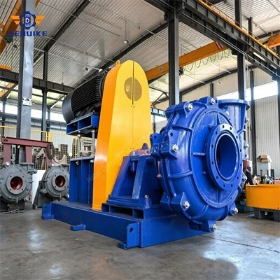
The typical structure of a slurry pump is as follows:
(1) Pump Head Assembly: The pump features a dual-layer casing (an inner and outer metal shell). The outer casing is split vertically, and the discharge outlet can be oriented in any of eight positions, spaced at 45° intervals. To effectively prevent leakage at the shaft seal, a combination of dynamic sealing, gland packing, or mechanical sealing is employed. A labyrinth-style clearance seal is provided between the impeller and the rear liner, which significantly reduces the amount of slurry leaking toward the stuffing box, thereby ensuring reliable sealing. The impeller is equipped with back vanes that discharge recirculating slurry, which improves volumetric efficiency, reduces backflow and erosion, and extends the service life of the flow-path components. A disassembly ring is included to facilitate maintenance and dismantling, preventing the need to cut the shaft in cases where components might otherwise be impossible to remove.
(2) Bearing Bracket Assembly: The bearing bracket features a horizontally split design. It has been optimized through both hydraulic and structural design to extend the service life of the bearings. By ensuring an appropriate distribution of radial and axial forces-and by carefully selecting the bearing type, model, and methods for cooling and lubrication-the design achieves low heat generation and a long service life for the bearings.
(3) Shaft Sealing System: The shaft sealing device provides a seal between the pump casing and the pump shaft. It prevents air from entering the pump and stops significant amounts of water from leaking out. Centrifugal slurry pumps typically employ a sealing arrangement consisting of an auxiliary impeller combined with a packed gland. This configuration functions as a hydrodynamic seal: the pressure head generated by the auxiliary impeller counteracts the leakage of fluid from the impeller outlet. Simultaneously, back vanes on the impeller shroud-in conjunction with a water-seal ring and packing-prevent the ingress of air. Furthermore, these back vanes and the water-seal ring serve to reduce pressure at the packing area, which also helps prevent impurities from entering the sealing assembly.
Structure Of Slurry Pumps
Next
No InformationPopular Products
-
![Horizontal Centrifugal Slurry Pump Anti-Wear High Chrome Alloy Impeller Back Plate Abrasion Resistant Mining]() Horizontal Centrifugal Slurry Pump Anti-Wear High Chrome Alloy Impeller Back ...Wear is the real cost driver in most slurry systems. When quartz-rich ore, crushed rock fines or heavy tailings pass...read more
-
![Wear Resistant Horizontal Slurry Pump]() Wear Resistant Horizontal Slurry PumpIntroduction: Operating Environments and Mechanics of Abrasive Wear in Slurry Systems Handling aggressive,...read more
-
![Horizontal Centrifugal Slurry Pump A05 High Chrome Alloy]() Horizontal Centrifugal Slurry Pump A05 High Chrome AlloyA Wear-Resistant Slurry Pump Built for Demanding Industrial Duties The Horizontal Centrifugal Slurry Pump A05 High...read more
-
![Heavy Duty Horizontal Centrifugal Slurry Pump]() Heavy Duty Horizontal Centrifugal Slurry PumpModern Slurry Transport Dynamics and Centrifugal Pumping Architecture Hydraulic pipeline transport of solids-laden...read more
Send Inquiry