1. Engineering Overview & Equipment Classification
Handling two-phase solid-liquid mixtures in industrial settings presents severe tribological challenges. Standard clear-water centrifugal pumps fail rapidly under these conditions due to abrasive scouring, particle impact erosion, and localized cavitation.
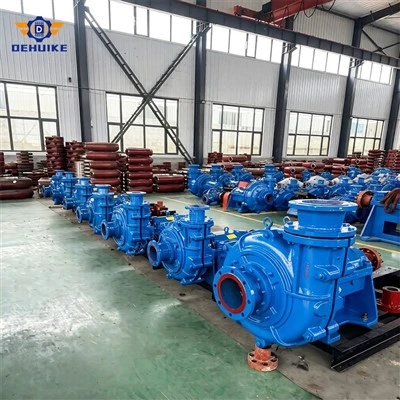
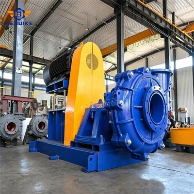
A horizontal slurry pump-commonly classified in international engineering standards as a heavy duty slurry pump-is a specialized, single-stage, end-suction, cantilevered centrifugal pump specifically configured to transport dense, highly abrasive, and corrosive slurries containing coarse suspended solids.
Designed for continuous industrial duties, modern industrial units (such as the standard DAH series) incorporate ultra-thick wet-end wear liners, robust dynamic sealing arrangements, and heavy-duty bearing assemblies capable of withstanding severe radial impact and hydraulic shock loads. These pumps reliably convey mineral slurries with solid concentrations reaching 60%–70%60%–70% by weight, maintaining high volumetric efficiency across extended operating campaigns.
2. Structural Anatomy & Mechanical Architecture
The standard DAH series horizontal heavy-duty slurry pump utilizes a split double-casing layout. This mechanical design segregates hydraulic pressure containment from abrasive sacrificial wear interfaces.
2.1 Double-Casing Construction (Outer Armor & Sacrificial Liners)
Outer Structural Casing: Cast from high-strength ductile iron (grade QT500-7) or structural cast steel, split vertically across the center. It safely withstands operating pressures up to and exceeding 3.6 MPa3.6 MPa, resisting hydraulic transients without mechanical deformation.
Internal Wet-End Liners: Comprising the volute liner, front liner (throatbush), and frame plate liner insert. These internal wear components are fully decoupled from the outer casing, enabling plant operators to perform in-situ replacements of worn components without replacing structural pressure boundaries.
2.2 Impeller Hydraulic Geometry
The heavy-duty closed impeller typically features 3 to 5 thick-section, twisted helical vanes with large internal clearances, permitting the passage of oversized rock fragments. Both front and back shrouds integrate outward-facing pump-out vanes (expelling vanes), which serve critical functions:
Generating reverse centrifugal pressure to reduce pressure on the shaft seal chamber;
Preventing abrasive particles from migrating into the sealing gap, minimizing sleeve wear;
Neutralizing axial hydraulic thrust to protect the thrust bearing assembly.
2.3 Cartridge Bearing Assembly with In-Situ Clearance Adjustment
The heavy-forged alloy steel shaft is supported by paired tapered roller bearings and heavy-duty cylindrical roller bearings within a rigid cartridge bearing housing. The assembly includes an external mechanical jacking mechanism. Maintenance personnel can adjust the axial clearance between the impeller shroud and the front throatbush externally, restoring design clearances and volumetric efficiency without disassembling piping or casing.
3. Solid-Liquid Two-Phase Hydrodynamic Principles
The operating physics of a horizontal slurry pump diverge substantially from Newtonian clear-water dynamics due to particle slip velocities, momentum transfers, and abrasive impingement:
Centrifugal Momentum Transfer: Driven by an electric motor or diesel engine, the rotating impeller accelerates slurry through its internal passages. Kinematic energy expands radially outward into the volute diffuser, where kinetic velocity head converts steadily into usable static pressure head.
Two-Phase Fluid Drag & Energy Dissipation: Solid particles possess greater inertia than the carrier fluid. As slurry navigates curved impeller passages, particles cross liquid streamlines and collide with metal surfaces (low-angle abrasive scouring along the vane face and high-angle impingement along the leading edge). Widened flow channels reduce velocity gradients, lowering turbulence and localized wear.
Cavitation Suppression: Entrained air and local pressure drops across the suction eye induce micro-cavitation. In slurry processing, cavitation bubbles implode against metal surfaces already subjected to abrasive micro-cutting, multiplying wear rates. Plant installations must maintain an available net positive suction head (NPSHaNPSHa) at least 1.3×1.3× higher than the pump's required net positive suction head (NPSHrNPSHr).
4. Metallurgy & Wear-Resistant Material Science
Material selection dictates equipment reliability and total cost of ownership (TCO). Industrial slurry pump components are categorized into high-hardness white iron alloys and shock-absorbing elastomeric polymers.
| Material Designation | International Benchmark | Microstructure & Chemistry | Hardness Rating | Recommended Application Environment |
|---|---|---|---|---|
| A05 High-Chrome White Iron | ASTM A532 Class III Type A (27% Cr) | Martensitic matrix with discontinuous eutectic carbides (Cr,Fe)7C3(Cr,Fe)7C3 | ≥58–62 HRC≥58–62 HRC | Severe impact-scour environments, primary cyclone feed, coarse tailings, quartz/hard-rock extraction (pH 5–12pH 5–12). |
| A49 Corrosion-Resistant Alloy | Hypoeutectic High-Cr (28-30% Cr + Mo/Ni) | Austenitic/martensitic dual-phase matrix + molybdenum micro-alloying | ≥45–52 HRC≥45–52 HRC | Flue gas desulfurization (FGD limestone slurries), acidic mining leach circuits, low-pH environments containing fine abrasives. |
| Natural Rubber Liners | High-Grade Engineered Natural Rubber | High-density cross-linked polymer network providing elastic deformation absorption | Shore A 40–5540–55 | Spherical or low-aspect-ratio fine particles (d50≤0.5 mmd50≤0.5 mm), secondary flotation circuits, and sand washing plants. |
5. Industrial Application Scenarios
5.1 Mining & Mineral Concentrators
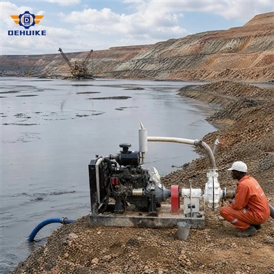
Typical Duties: SAG/ball mill discharge, hydrocyclone classification feed, flotation tailings transfer, thickener underflow.
Slurry Dynamics: High concentration (45%–65%45%–65% solids by weight), angular quartz particles, abrasive slurries with large top sizes.
Standard Fitment: Heavy-duty DAH design fitted with A05 high-chrome wet ends, large-diameter expeller dynamic seals, and reinforced baseframes.
5.2 Coal-Fired Power Utilities (FGD & Ash Sluicing)
Typical Duties: Bottom ash hydraulic sluicing, coal washing plant waste transfer, absorber tower limestone recirculation.
Slurry Dynamics: High temperatures (50–70∘C50–70∘C), erosive ash particles, and high chloride ion concentrations (Cl−≤60000 ppmCl−≤60000 ppm).
Standard Fitment: A49 or duplex alloy wet-end liners matched with dedicated mechanical seals utilizing external barrier flushes to counter chloride stress-corrosion.
5.3 Metallurgical Refining & Steel Mills
Typical Duties: Blast furnace slag quenching, converter secondary wastewater handling, continuous casting scale pit evacuation.
Slurry Dynamics: Dense, sharp-edged iron oxide flakes, fluctuating feed temperatures, high-impact hydraulic conditions.
Standard Fitment: Heavy cast iron volute casings fitted with high-hardness Cr27 closed impellers and grease-lubricated bearing cartidges.
5.4 River Dredging & Sand Reclamation
Typical Duties: Harbor dredging, channel reclamation, long-distance sand and gravel booster stations.
Slurry Dynamics: Broad particle distribution (sand, pebbles, and clay), high variable system static heads, high pipe friction losses.
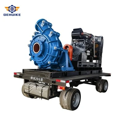
Standard Fitment: Large-passage impellers driven directly by high-torque electric motors or diesel engines via speed-reduction gearboxes.
6. Preventive Maintenance & Operational Protocols
Proactive maintenance protocols reduce unplanned downtime and optimize wear-part life cycles across continuous operations:
6.1 Routine Axial Clearance Adjustment
As the throatbush and front impeller shroud wear, internal recirculation increases, degrading hydraulic output and accelerating throatbush cutting wear.
Action Protocol: Every 300–500300–500 operational hours, loosen the bearing cartridge clamping bolts. Using the rear adjustment screws, advance the shaft assembly forward until the impeller touches the front throatbush. Then, back off the assembly 0.5–1.0 mm0.5–1.0 mm and re-clamp firmly. This simple action restores design clearances and baseline volumetric efficiency.
6.2 Bearing Lubrication & Thermal Baselines
Grease Systems: Use high-quality lithium-complex grease (NLGI Grade 2 or 3). Maintain fill levels at 1/31/3 to 1/21/2 of the bearing cavity volume to prevent churning-induced overheating.
Oil-Bath Systems: Maintain the sight glass at the mid-level line. Maximum allowable bearing temperature should not exceed 75∘C75∘C, with an ambient rise limit of 40∘C40∘C. Overall vibration levels must remain below 4.5 mm/s RMS4.5 mm/s RMS per ISO 10816 standards for industrial machinery.
6.3 Shaft Sealing Protocols
Expeller Dynamic Seal: Best suited for flooded suction lines where suction head does not exceed 15%15% of discharge head. Ensure the static lip seals or dry packings are intact to prevent leakage during shutdowns.
Flushed Gland Packing: Clean external flush water must enter the lantern ring at a regulated pressure 0.1 MPa0.1 MPa (15 PSI) above the internal pump discharge pressure. Regulate gland bolts to maintain a steady lubricating drip rate of 30–6030–60 drops per minute.
7. Root-Cause Field Troubleshooting Matrix
| Problem Statement | Probable Root Cause (Mechanisms) | Field Corrective Action Plan |
|---|---|---|
| Excessive Vibration & Low-Frequency Noise | 1. Foundation bolt looseness or grout deterioration. 2. Shaft misalignment (radial angular error >0.1 mm>0.1 mm). 3. Severe hydraulic cavitation due to blocked suction piping. 4. Asymmetrical impeller wear causing dynamic unbalance. |
1. Retorque all anchor bolts; verify foundation mass stiffness. 2. Re-align pump and driver shafts using dial indicators or laser tools. 3. Clear intake trash racks; reduce suction line drag losses. 4. Inspect impeller; re-balance rotor assembly or replace worn components. |
| Insufficient Flow Rate and Discharge Head | 1. System resistance calculated lower than actual piping head loss. 2. Drive ratio error or excessive V-belt slippage. 3. Large axial clearance between impeller and throatbush. 4. Air entrainment through suction line flanges. |
1. Recalculate true system curves and adjust pump running speed. 2. Tension drive belts or adjust variable frequency drive (VFD) output. 3. Perform mechanical axial clearance reset (0.5–1.0 mm0.5–1.0 mm). 4. Inspect suction gaskets; eliminate negative-pressure leak paths. |
| Severe Shaft Seal Leakage | 1. Hardened packing rings; shaft sleeve grooved by abrasive grit. 2. Seal flush water pressure below pump internal chamber pressure. 3. Expeller or expeller ring vanes worn beyond clearance limits. 4. Mechanical seal faces cracked or jammed with solids. |
1. Replace hardened packing rings and install hard-faced alloy sleeve. 2. Elevate clean seal water pressure to 0.1 MPa0.1 MPa over discharge. 3. Inspect dynamic expeller assembly; replace if clearances are excessive. 4. Service mechanical seal; flush cavity and clean seal faces. |
| Driver Motor Overloading | 1. Slurry specific gravity or solid concentration higher than design. 2. Discharge head too low, shifting pump to high-flow run-out. 3. Mechanical binding between rotating elements and casing liners. |
1. Sample slurry density; recalibrate operating speed or upsize motor. 2. Throttle discharge valve to bring duty point back toward BEP. 3. Rotate shaft manually; reset internal running clearances. |
8. Engineering FAQ (Structured for Search & AI Overview)
Q1: What differentiates a heavy-duty horizontal slurry pump from a standard water pump?
Direct Engineering Answer: A heavy-duty horizontal slurry pump features double-casing construction, extra-thick Cr27 high-chrome or rubber liners, and a wide-passage closed impeller with back expelling vanes. In contrast to clear-water pumps that quickly erode in abrasive services, slurry pumps handle dense solids concentrations up to 70%70% by weight, using low-velocity internal channels to minimize mechanical cutting and abrasive wear.
Q2: Why is operating near the Peak Efficiency Point (BEP) critical for slurry pumps?
Direct Engineering Answer: Slurry pump liners wear fastest when operating far from their Peak Efficiency Point (BEP). Operating below 80%80% or above 110%110% of BEP generates internal flow recirculation, secondary vortices, and flow separation. These flow disturbances cause sharp particles to strike liner and impeller surfaces at steep angles, causing localized gouging, accelerated casing wear, and premature equipment failure.
Q3: Which shaft seal should be specified: dynamic expeller, packed gland, or mechanical seal?
Direct Engineering Answer:
Expeller Dynamic Seal: Best for remote mine sites where clean external seal water is unavailable and suction pressure is low to moderate (<15%<15% of discharge head).
Packed Gland Seal: Standard choice for broad industrial applications; requires continuous clean flush water at 0.1 MPa0.1 MPa above discharge pressure.
Balanced Mechanical Seal: Selected where zero environmental leakage is mandated or slurry dilution is impermissible; requires clean barrier fluid flush systems.